
INC Cloud
General User Guide
INC Cloud
General User Guide
INC Cloud is Intelbras' cloud management platform for managing access points from the RW and Future lines, select compatible switch models from the Future line, and manageable switches from the S23 and S33 lines. Using the platform is free, with no contract or license required.
The platform serves to centralize the management of your network devices in a practical way, allowing real-time monitoring, creation of Wi-Fi networks with authentication portals, and tracking the logical topology of adopted equipment.
Provisioning is automatic: as soon as the cloud-supported device is connected to the internet with factory default settings, it communicates with INC Cloud and can be adopted to receive its centralized configurations.
INC Cloud Getting Started
This section describes the fundamental steps to start using the INC Cloud platform, covering the account creation process, organizing your infrastructure by creating sites, and the device adoption flow.
Account creation
To start using INC Cloud and manage your devices centrally and free of charge, the first step is to create an administrator account on the platform.
Create account
- Go to inccloud.intelbras.com.br. The login page will be displayed.
- Click on Register.
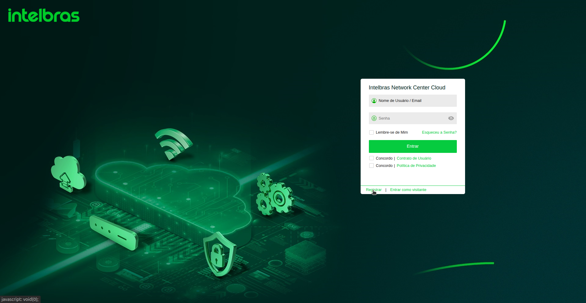
Figure: Login Page — Link to register a new account highlighted at the bottom.
- Fill in the fields:
- Username — a unique identifier that you can use to log in instead of the email address. The username must contain 6 to 32 characters, start with a letter, and accepts only letters, digits, and underscores (_).
- Email — will be used to activate the account and can be used to log in.
- Password — create a secure password and repeat it in the confirmation field.
- Read the user agreement and privacy policy, check the agreement boxes (Agree), and click on Finish.
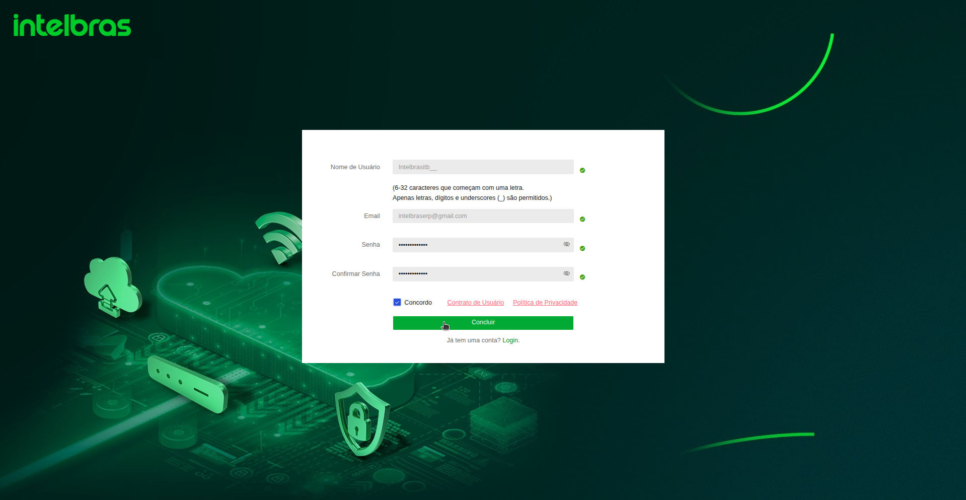
Figure: Registration Form — Sign-up fields completed and terms accepted.
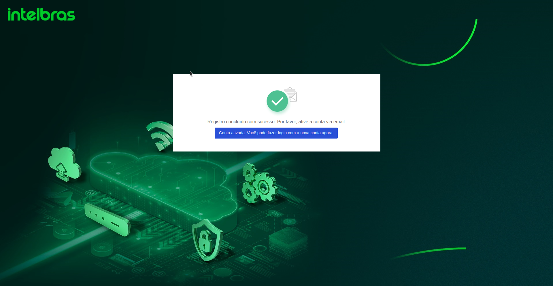
Figure: Registration Successful — Confirmation alert showing that account activation is required.
Once the registration details are submitted, the INC Cloud platform will display a notice requesting account activation via the provided email address. Follow the steps below to complete this process:
Activate the account
- Access the registered email. You will receive a message from Intelbras (sender
irs@irs.intelbras.com.br) with the subject Intelbras Email Binding.

Figure: Mail Inbox — Account activation email received from Intelbras.
- Open the email and click the blue link Click here to activate the account.
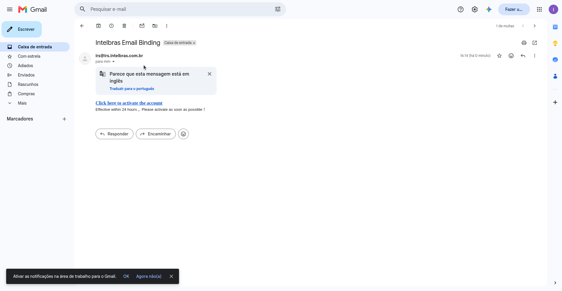
Figure: Verification Email — Link to perform account binding inside the message body.
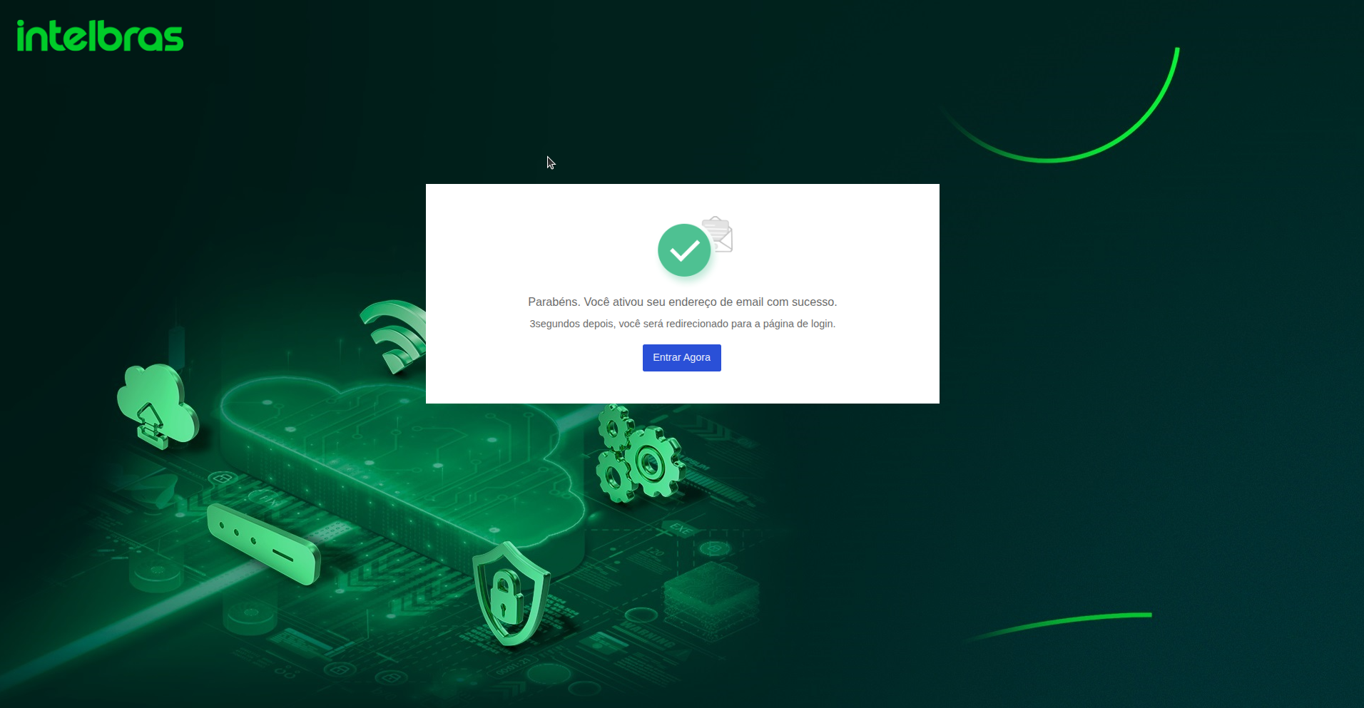
Figure: Activation Successful — Notification page confirming that the email address is verified.
Upon clicking the link in the email, a new tab will open displaying a message confirming the successful activation of your account. You will be automatically redirected to the login page after a few seconds, or you can click the blue Sign In Now button to proceed immediately.
Note: Email activation is mandatory. Platform access is only enabled after activating the email address.
Log in
- Go back to inccloud.intelbras.com.br or click the Sign In Now button shown after activation.
- Enter the registered username or email and the respective password.
- Check the agreement boxes for User Agreement and Privacy Policy, then click on Sign In.
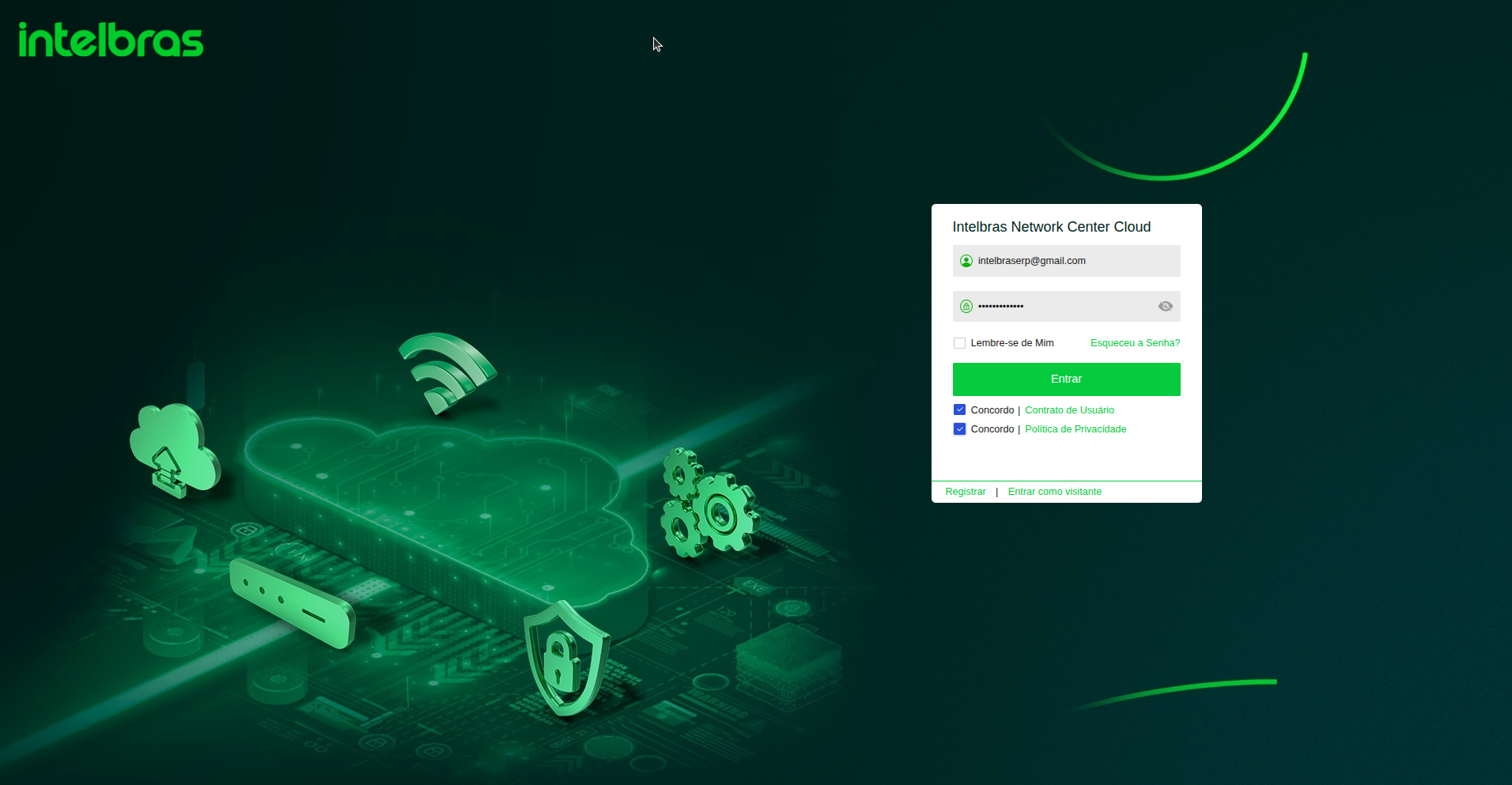
Figure: Sign In Panel — Credential entry and user policy acceptance selection.
On the login screen, enter your activated credentials and select the checkboxes confirming agreement with the terms of use and privacy policy. The Sign In button will become enabled to proceed.
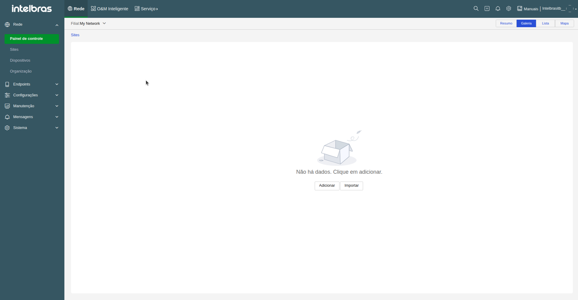
Figure: Main Dashboard — Empty control panel screen displayed after logging in for the first time.
Upon successfully logging in for the first time, the INC Cloud home dashboard will be displayed. Since this is a new account, the dashboard will be completely empty, indicating that no sites are configured or devices adopted under your account. From this point, the next step is to structure your network locations and adopt your equipment.
Note: The username and the email are interchangeable in the login field. Keep both in mind to avoid access issues in the future.
Organizational structure (company, branches, and sites)
In INC Cloud, network infrastructure is organized in a three-level hierarchy (Organization, Branches/Units, and Sites). This structure allows segmenting management by company, region, or physical environment, making it easier to apply network policies and configurations.
The hierarchy of INC Cloud has three levels:
- Organization (Company) — represents the company or group. Created automatically with the default name My Network.
- Branches / Units — subgroups within the organization, such as headquarters, regional offices, or business units.
- Sites — physical environments within a branch (e.g., departments, rooms, auditoriums) where devices are added.
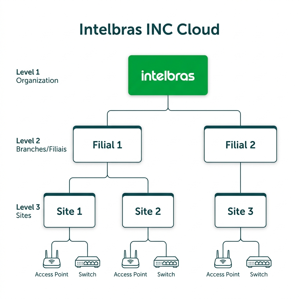
Figure: Organizational Topology — 3-level hierarchy diagram (Organization → Branches → Sites and Devices).
1. Rename the organization
The first step in structuring your account is customizing the main organization name. By default, the platform assigns the name My Network, which can be changed to your company or enterprise group name.
- Access Organization. The default organization My Network will be displayed.
- Select the organization, click the edit button and enter your company's name. Ex: Intelbras.
- Click OK to save.
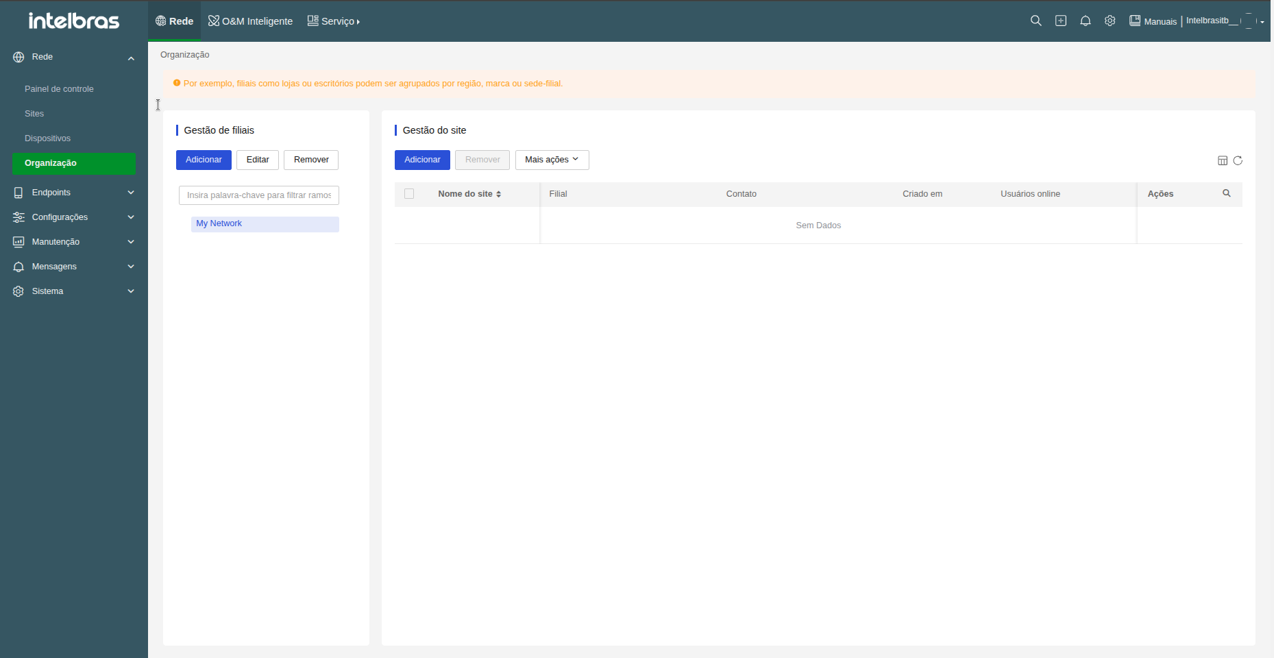
Figure: Organization Screen — Management menu displaying the default initial organization.
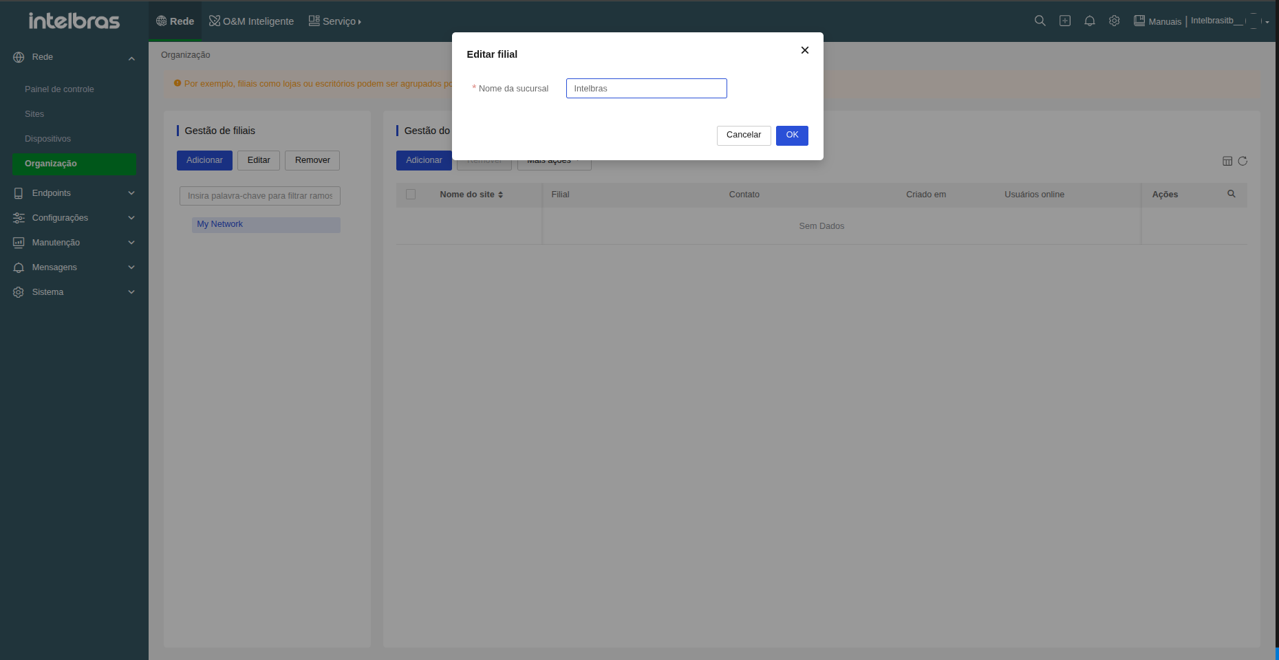
Figure: Updated Organization — Structure after renaming the main organization and adding two branches.
Once the organization is renamed, your company identifier will be displayed at the top of the hierarchy. Next, you can create branches or units to represent your headquarters, offices, or physical stores.
2. Create branches or units
Creating branches or business units allows organizing the company into regional or operational subgroups (e.g., Headquarters, Branch 1, Branch 2). This division facilitates decentralized management and access privilege assignment.
- Within Branch Management, click Add.
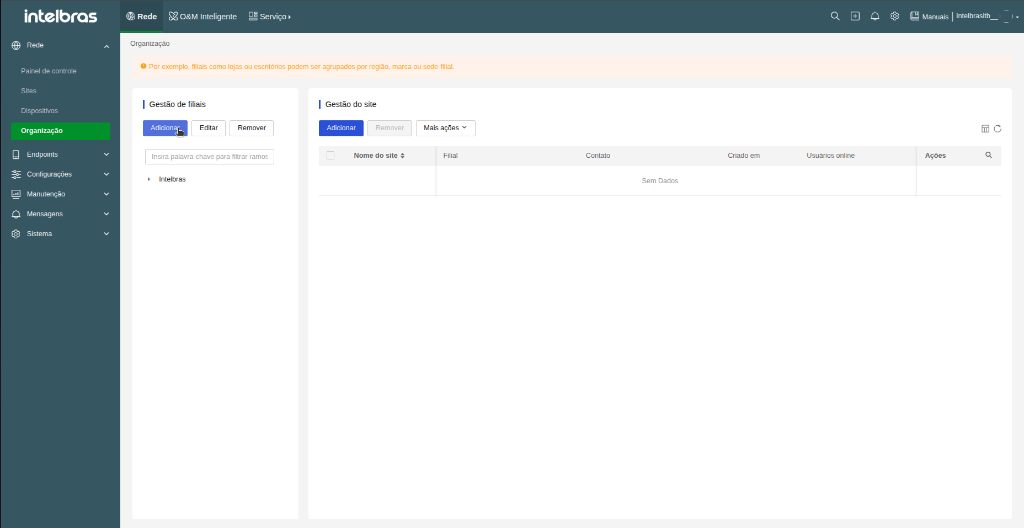
Figure: Branch Management — Click the blue Add button to create a new branch.
In the Add branch modal, enter the name corresponding to the branch or business unit of the company, and click OK to confirm.
- Enter the unit name (e.g., Branch 1, Branch 2) and click OK.
- Repeat for each desired unit.
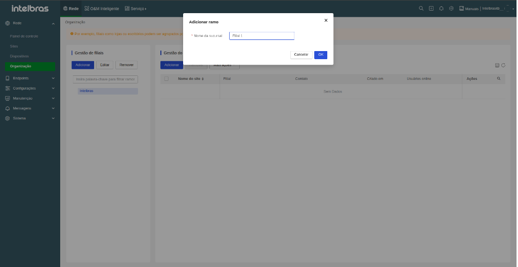
Figure: Branch Window — Entering the name of the new branch to be created.
After creating the required branches, your company's organizational structure will be set up in the management side panel. With the organization and branches properly structured, you can now create physical sites within each unit to allocate equipment.
3. Create a site
Sites correspond to actual physical locations (such as offices, meeting rooms, stores, or warehouses) where network devices will be installed. All access policies and network settings are applied per site.
- Navigate to the branch or unit where you want to create the site and click Add under Site Management. The site creation wizard will be displayed.
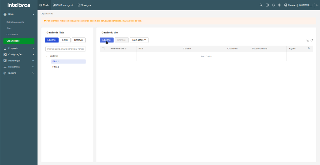
Figure: Site Management — Click the blue Add button to start creating a new site.
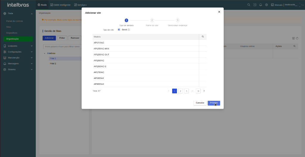
Figure: Wizard Step 1 — Selection of the General site type.
- Fill in the fields:
- Site name — up to 20 characters, no leading spaces.
- Branch — select the branch or unit the site belongs to (in this example, Branch 1).
- Industry — select the business segment or leave as Others.
- Contact and Description — optional fields.
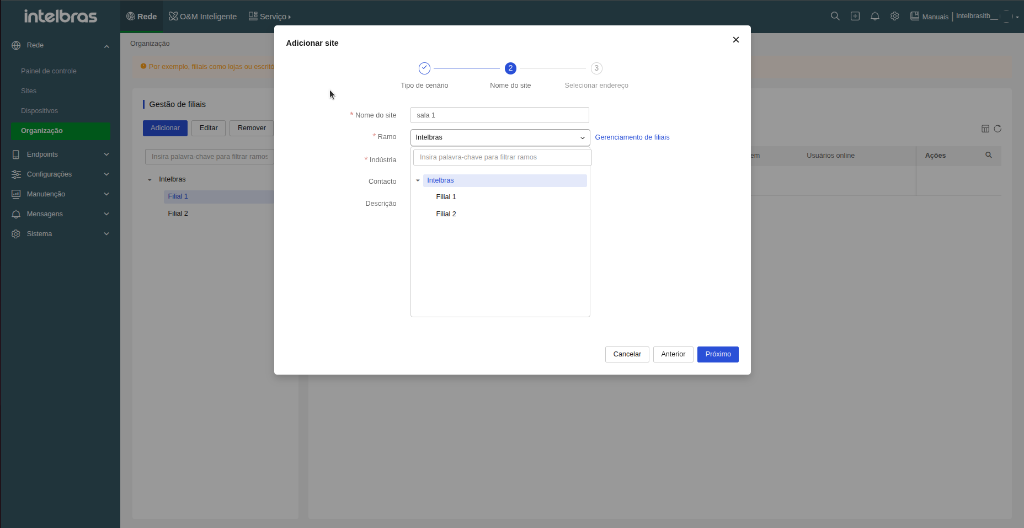
Figure: Branch Selection — Configured branch options available for the site.
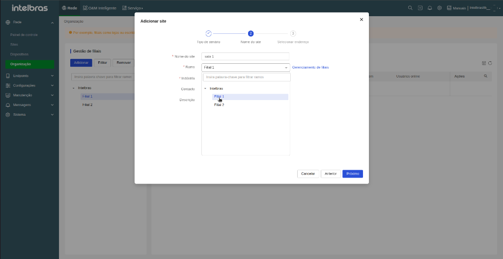
Figure: Branch Assignment — Selecting the corresponding branch for the new site.
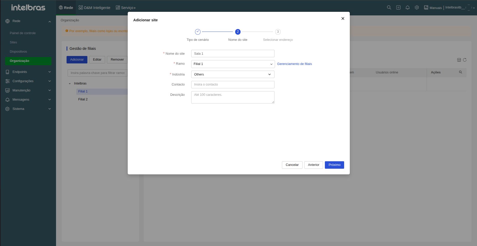
Figure: Site Information — Site name completed and linked to the correct branch.
- Click Next. If desired, specify the physical location of the site on the map and click OK.
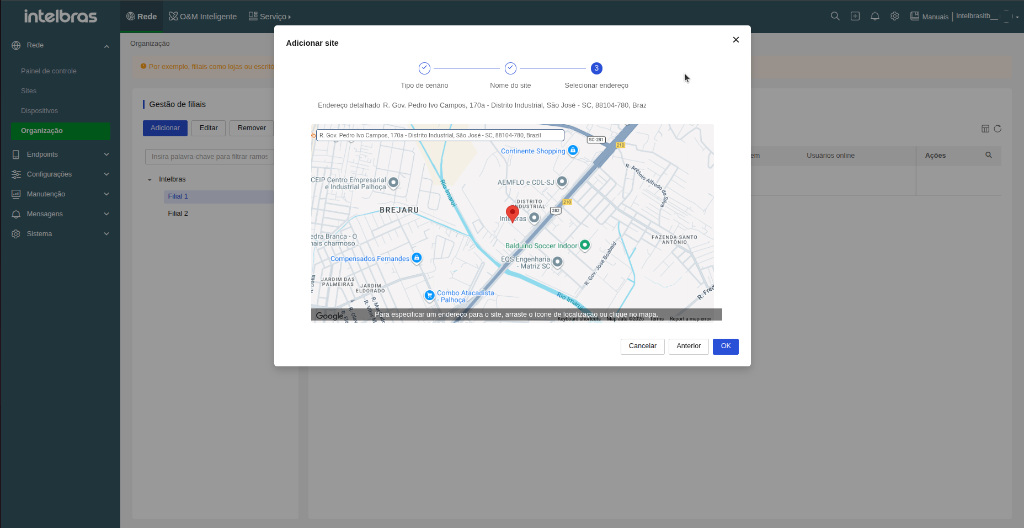
Figure: Physical Location — Selecting and marking the site address on the map.
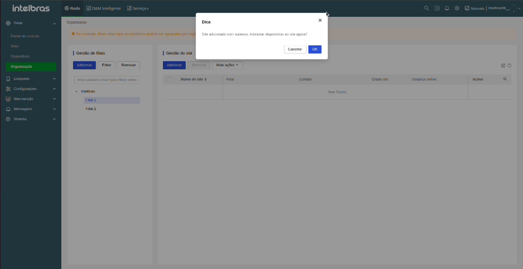
Figure: Creation Confirmation — Site created and notice for immediate adoption of new devices.
- Repeat for each additional desired environment.
Once site creation is complete and the full hierarchy is configured (Organization → Branches → Sites), your cloud infrastructure is ready to receive equipment. In the next section, you will see how to perform Device Adoption to link hardware to their respective sites.
Tip: Plan and document your network hierarchy before creating sites. Adding a device to the wrong site requires manually moving it later.
Device adoption
After structuring your network locations (Organization → Branches → Sites), the next step is performing Device adoption. Adoption physically links equipment to their respective sites using the device's Serial Number (S/N), located on the label on the back or bottom of the hardware.
You can add devices to sites through two different navigation paths in the INC Cloud interface:
-
Through the Sites / Organization tab (side menu Network > Organization): select the desired branch and site, then click the Add Device button on the site panel.
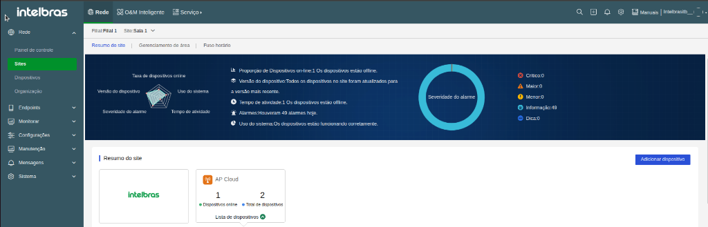
-
Through the Devices tab (side menu Network > Devices): displays the grouping screen with the full list of all devices registered in your account. On a new account, the table will initially be empty. Simply click the blue Add Device button in the upper right corner.

Upon clicking Add Device, the adoption modal window will open for filling in equipment details:
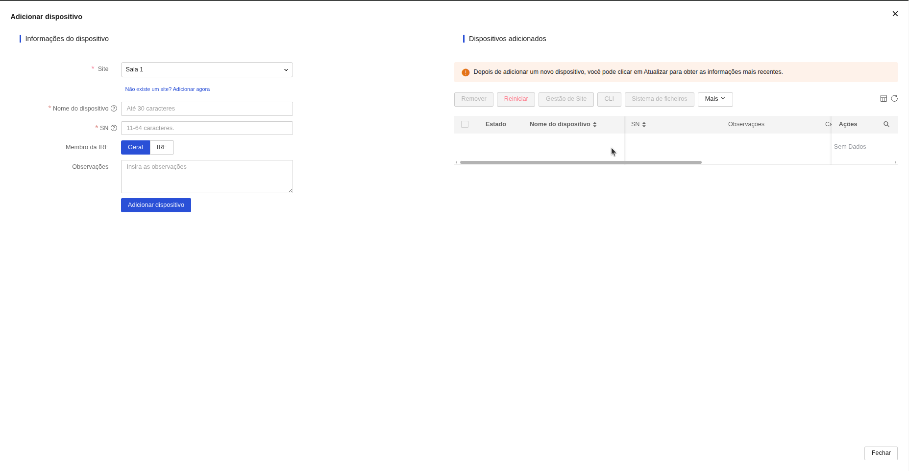
Figure: Adoption Window — Form for registering new devices in INC Cloud.
1. Adoption of APs and Controllers (APs / ACs)
Adoption of Access Points (RW and Future series) and Access Controllers (ACs) is performed by filling out the adoption form with the Serial Number (S/N) printed on the hardware label. Warning: Access Points (APs) and Access Controllers (ACs) must never be added with the IRF option (this feature is exclusive to switches and must be kept as General).
- Open the adoption window and select the correct Site where the device will be assigned.
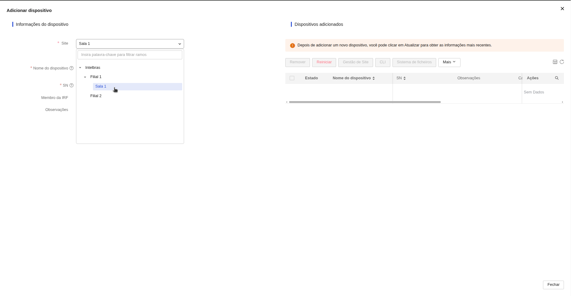
Figure: Site Selection — Choosing the target site within the company hierarchy.
- Enter a Device name for identification in the platform.
Note: Any lowercase letters entered in the device name will be automatically converted to UPPERCASE once the device is successfully added.
- Enter the 11 to 64 character Serial Number (SN) printed on the equipment label.
- Fill in the Description field (optional) with notes on physical location.
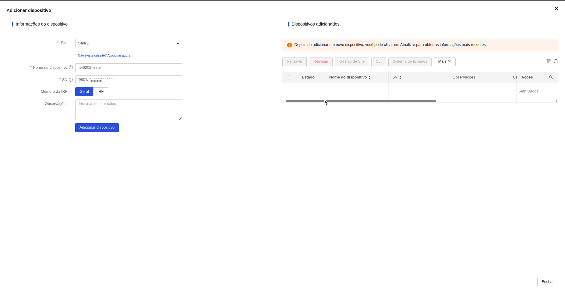
Figure: Form Completion — Entering device identifier name and serial number.
- Click Add Device to complete adoption.
2. Adoption of Switches
Adoption of managed switches (select compatible models from the Future line, and S23 and S33 series) follows the same basic form as APs, with the exclusive addition of the IRF stacking feature.
Note: Not all switch models in the Future line support INC Cloud adoption; ensure that the specific hardware model supports cloud management.
Alert (IRF Member - Exclusive for Switches): The IRF Member option is an exclusive feature for managed switches (select compatible models from the Future line, as well as S23 and S33 series). IRF (Intelligent Resilient Framework) allows grouping multiple physical switches to operate as a single virtual logical device. Important: The user should only select the IRF option if they are actually going to use the physical stacking feature. Otherwise, the adoption process should be performed normally, leaving the IRF Member option as General (default).
If you are adding a switch that is part of an IRF group, follow these steps:
- In the IRF Member field, change the selection from General to IRF. The Add Group button will appear.

Figure: IRF Configuration — Selecting IRF mode and button to add a stacking group.
- Click Add Group, enter the stacking group name (e.g., GROUP 1) in the confirmation popup, and click OK.
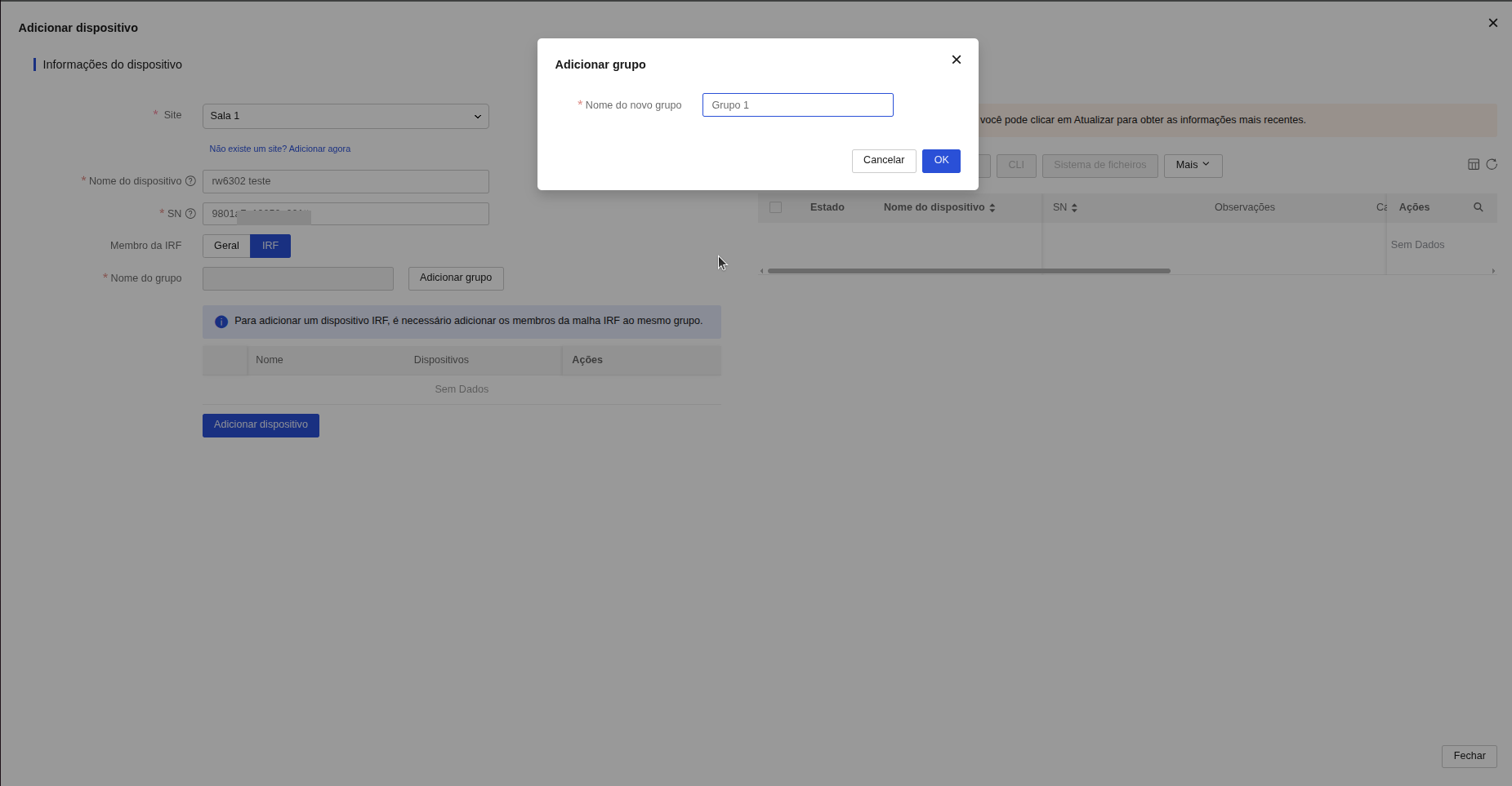
Figure: Creating IRF Group — Defining group name for switch stacking.
- Select the created IRF group from the list and click Add Device.
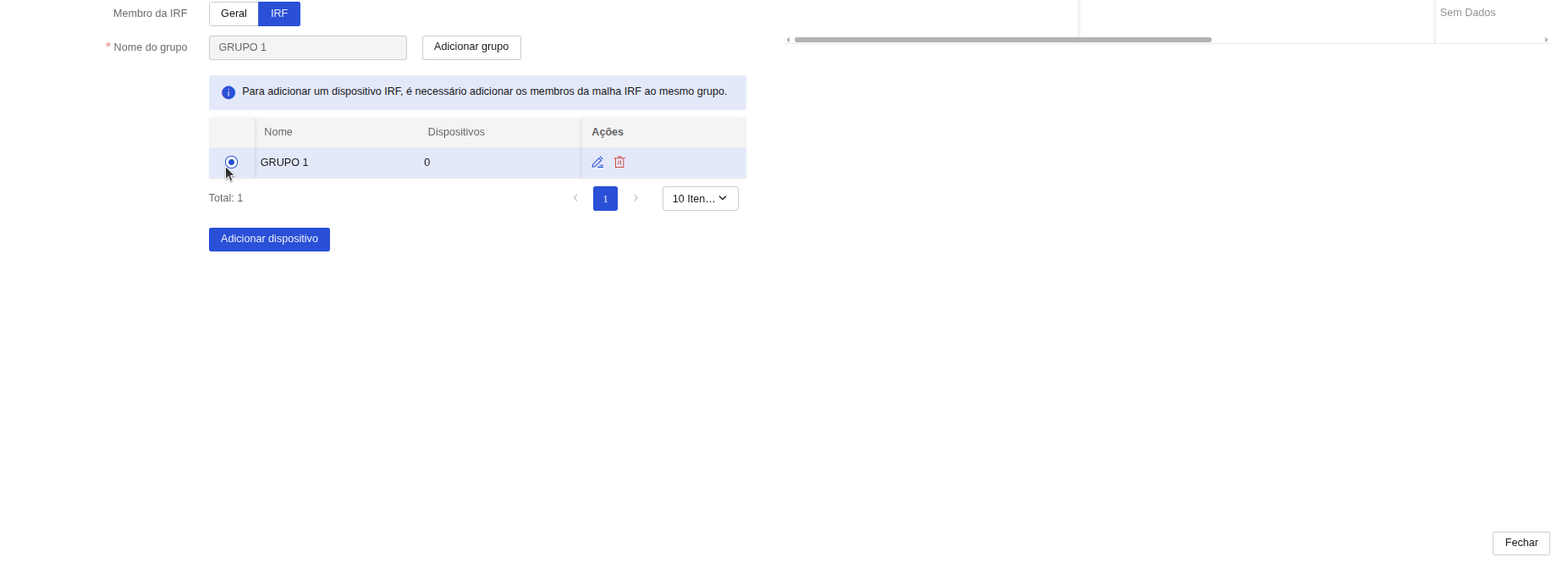
Figure: Selected IRF Group — Linking switch to configured stacking group.
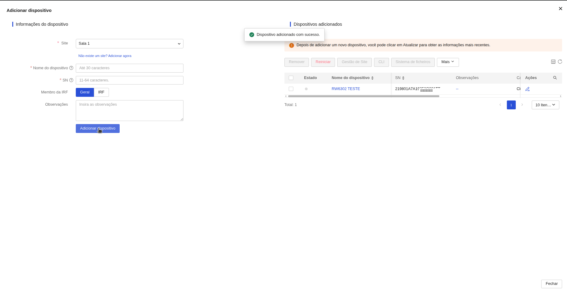
Figure: Success Confirmation — Confirmation message and device registered in the right list.
Note: The device can be added to the platform even if it is powered off. Synchronization with the cloud will occur automatically as soon as the equipment connects to the internet, and its status will turn green (online).
3. Adoption of Legacy APs (Zeus Line / Previous Generation APs)
Access Points from legacy lines or with standard Zeus firmware (such as the AP 1800 AX, AP 3000, and equivalent families) are fully compatible with the INC Cloud platform. To integrate them and enable complete cloud management (SSID changes, passwords, radio control, and remote firmware updates), you must perform an update using the integration firmware and register the device on the platform using its MAC address.
To check the full list of compatible Access Points and Zeus integration firmwares for INC Cloud, refer to the official document: Zeus INC Cloud Firmware List (PDF).
Step-by-step procedure for adopting legacy APs:
- Download the Zeus / INC Cloud Integration Firmware:
- Access the official Intelbras website (intelbras.com.br) or use the Zeus INC Cloud Firmware List (PDF) to obtain the firmware links for your exact AP model (e.g., AP 1800 AX).
- Navigate to the Downloads section and download the file titled "Firmware de integração Zeus INC Cloud" (required to make the original Zeus AP firmware compatible with the INC Cloud platform).
- Connection and IP/MAC Address Identification:
- Connect and power the AP on the local network via PoE (with an active DHCP server on the network).
- Use the Reset Tools utility on your computer to scan the local network and identify the IP address and MAC address assigned to the device.
- Tip: On models such as the AP 1800 AX, the physical label containing the MAC address and default factory password is located under the mounting bracket.
- Access Local Web UI and Update Firmware:
- Open a browser and access the AP's local IP address (default username:
admin, password on the label). - Change the default password upon initial login as prompted by the system.
- Navigate to System > Firmware Upgrade.
- Manually select the integration firmware file downloaded in Step 1 and confirm the upgrade. Wait for completion and automatic device reboot.
- Open a browser and access the AP's local IP address (default username:
- Factory Reset:
- After rebooting with the new firmware, access the AP's web UI again.
- Go to System > Backup & Restore and click Restore Factory Settings. This step is essential to ensure clean cloud communication settings take effect.
- Device Registration in INC Cloud using MAC Address:
- Log into the INC Cloud dashboard, select the target Organization and Site, and click Add Device.
- In the device addition window, enter the desired device name and enter its MAC Address into the SN field.
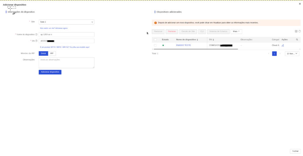
Figure: Entering device name and MAC address into the SN field.
- Click the link Is it a Wi-Fi 4 / Wi-Fi 5 / Wi-Fi 6 AX product? Choose your model here! to open the model selection modal window.
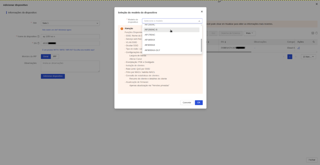
Figure: Modal window for selecting the corresponding legacy AP model.
- Select the device model (e.g., AP1350AC-S, AP1800AX, or AP3000AX) and click OK. INC Cloud will automatically convert the MAC into the corresponding serial number (SN).
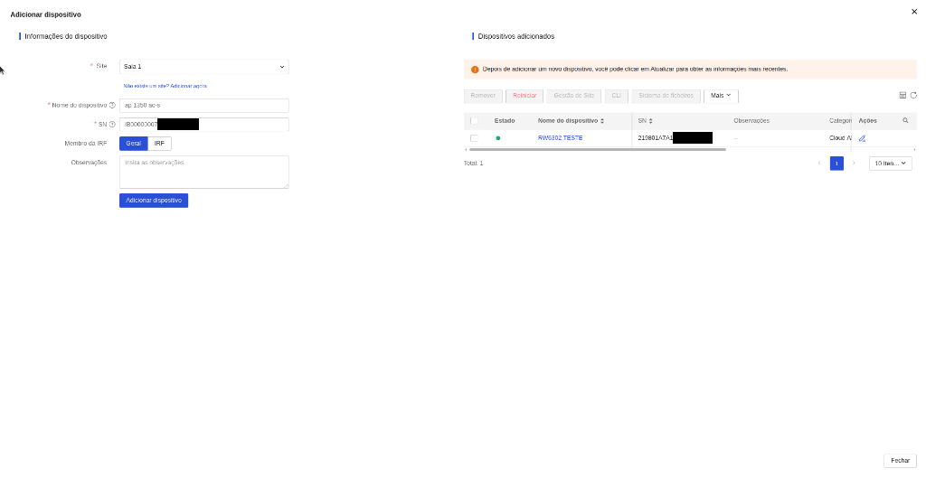
Figure: Serial number automatically filled after selecting model.
- Click Add Device to save.
- Synchronization and Cloud Management:
- After saving, the AP will connect to INC Cloud and the device status will change to Green (Online).
- The platform will display the serial number, category, model, and firmware version. The AP will automatically adopt the site's configuration and be ready for centralized cloud management.
Note: To add any device to a branch or unit, ensure that the corresponding site has already been created.
Configure wireless services
Follow the steps below to configure Wireless (WLAN) services in INC Cloud, defining parameters such as SSID and encryption, and linking portal authentication settings centrally to managed devices.
SSID Settings for Cloud APs
Use this procedure to access the SSID (wireless network) configuration screen on cloud-managed APs (Cloud APs).
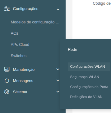
In the left side menu, go to Network > Settings > Cloud APs > WLAN Settings and then select the Wi-Fi Settings tab. Select the Branch and the Site to which you want the configuration to be applied.
On the main Wi-Fi Settings screen, you will find quick configuration buttons at the top of the table and action buttons under the Actions column:

Quick configuration buttons:
| Button / Feature | Description and How it Works |
|---|---|
| Add | Launches the flow to create a new SSID. |
| Remove | Permanently deletes selected SSIDs. |
| Enable service / Disable service | Instantly turns wireless signal transmission on or off for the selected networks. |
| Hide SSID / Show SSID | Instantly changes the visibility of the selected networks (public or hidden). |
| Task schedule |
Opens automated scheduling options for the selected SSIDs:
|
Action buttons:
| Action Button / Icon | Description and How it Works |
|---|---|
Edit |
Opens the basic and advanced configuration modal for an already created SSID for modification. |
Define client allow and deny list |
Allows configuring access control by physical address (MAC) for the selected SSID:
|
Design authentication templates |
Opens the Captive Portal visual editor to customize the design, logo, colors, and terms of use of the login page shown to users on this SSID. |
Define access control |
Configures network Access Control Lists (ACLs) to allow or block wireless clients' traffic to specific local or external destinations (IPs/subnets):
|
Delete SSID |
Permanently deletes the selected SSID. |
Create an SSID
On the Wi-Fi Settings screen, click Add. In the configuration window that opens, define the network name (in the SSID field) and the radio type. Filling in these two options is the minimum required to create the network by clicking OK.
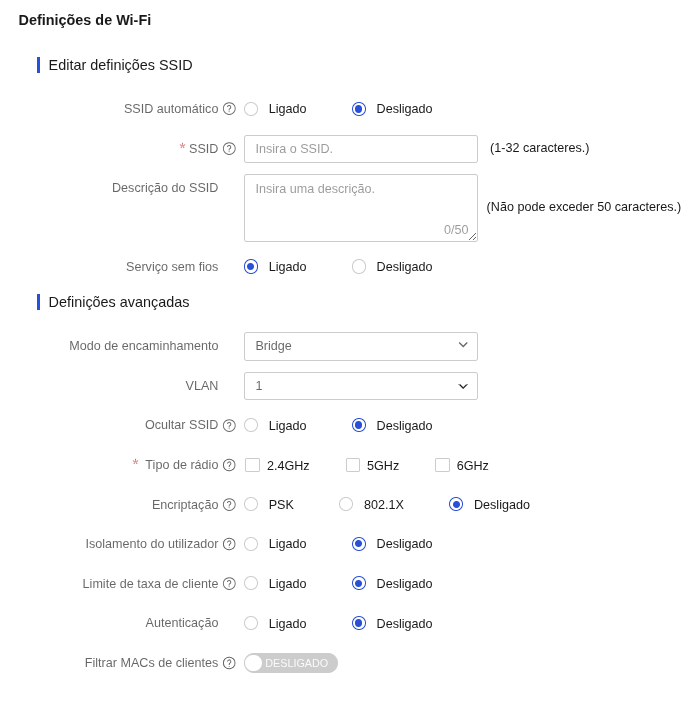
By default, the SSID comes enabled. If you wish to create it disabled initially, change the Wireless service field to Off (you can also disable the SSID later by clicking the Disable service button on the main screen).
If desired, you can also configure other additional options for the Wi-Fi network, such as the authentication portal, encryption, and the forwarding mode. Each of these additional parameters is detailed in the table below:
Key Network Settings and Parameters
| Parameter | Description and How it Works |
|---|---|
| Automatic SSID |
Combines the name configured in the SSID field with each AP's alias in the format [SSID]_[AP_Alias] to make it easier to identify where the client is connecting from.
Important: The final automatically generated name cannot exceed the physical limit of 32 characters. Avoid configuring very long initial SSID names to prevent provisioning failures on the APs. |
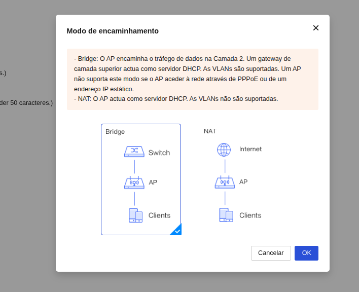
| Forwarding mode |
Defines the logical path and how the data traffic of Wi-Fi clients will be delivered to the physical local network infrastructure connected to the AP:
|
| VLAN | Specifies the numeric ID of the local VLAN (available only in Bridge forwarding mode) to which users connected to this SSID will belong. This allows separating logical routing and physical security policies on the company's router. |
| Encryption |
Defines the wireless security protocol and encryption of data transmitted over the air between the AP and client devices (such as WPA2/WPA3 Personal/Enterprise or Open Network).
Captive Portal Note: If you plan to use Captive Portal authentication, encryption must be set to Off (Open Network), as user validation will occur on the Web page after connection. |
| User isolation |
Isolates clients accessing the same SSID provided by the same AP, preventing them from starting to communicate directly with each other (blocks Layer 2 lateral traffic).
Compatibility Note: Only some cloud-managed AP models support this feature. For more information, see the INC Cloud Release Notes. |
| Filter client MACs |
Allows restricting or allowing physical association to the SSID based on the client devices' physical address (MAC Address):
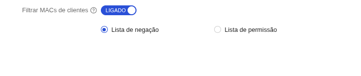

Note: This feature directly depends on the AP hardware support. Only specific cloud-managed AP models support this MAC filter. To check compatibility, see your device's release notes in INC Cloud. |
Edit an existing SSID
Use this procedure to modify the settings of a wireless network (SSID) that has already been created, allowing you to change the network name, security mode, traffic VLAN, bandwidth limits, or enable the authentication portal.
Procedure:
- On the left sidebar, navigate to Network > Settings > Cloud APs > WLAN Settings and make sure you are on the Wi-Fi Settings tab.
- In the wireless networks table, locate the SSID you want to modify and, in the Actions column, click the Edit icon (pencil).
- A modal window containing all SSID settings will open. Make the necessary changes in the desired fields (such as changing the network name in the SSID field, modifying security under Encryption, or managing advanced parameters).
- After adjusting all the necessary settings, click OK to save the changes.
Important: Changing critical security parameters (such as password or encryption type), VLAN, or disabling the service will force the temporary disconnection of all clients currently connected to this SSID. Devices will need to reconnect and re-authenticate to the network using the new credentials.
Remove an SSID
Perform this task to delete an SSID and stop its wireless network broadcast.
Restrictions and guidelines
Removing an SSID disconnects all clients currently associated with it. Make sure no critical devices are connected before proceeding.
Procedure
- Go to Network > Cloud APs > WLAN Settings > Wi-Fi Settings.
- Locate the SSID you want to remove in the list.
- Click the Delete icon (trash bin) corresponding to the SSID.
- Confirm the deletion by clicking OK in the confirmation window.
Enable and disable an SSID
You can enable or disable the Wi-Fi signal broadcast of an SSID at any time without deleting the network configuration. Disabling the service is useful for temporary maintenance or scheduled suspension of network access.
How to disable an SSID:
- Go to Network > Cloud APs > WLAN Settings > Wi-Fi Settings.
- In the wireless network table, check the box (checkbox) next to the SSID you want to disable.
- At the top of the table, click the Disable service button.
- The network status will change to inactive, and the Wi-Fi signal broadcast will stop immediately for clients.
How to enable an SSID:
- Go to Network > Cloud APs > WLAN Settings > Wi-Fi Settings.
- Check the box next to the inactive SSID.
- At the top of the table, click the Enable service button.
- The Wi-Fi signal broadcast will be re-established immediately, and authorized clients can connect to the network again.
Configure MAC filtering per SSID
The MAC Filtering feature allows you to control wireless network access by authorizing (permit list / whitelist) or blocking (deny list / blacklist) specific devices based on their physical MAC addresses.
Restrictions and guidelines
- The rule for a MAC whitelist or secondary list can take effect: On a Wi-Fi 6 device site, the maximum number of supported MAC addresses is 2047. On a Wi-Fi 5 device site, the maximum number of supported MAC addresses is 64. Any excessive entries beyond the specifications have no effect.
- The following MAC address formats are supported:
AA-cc-bB-67-e3-00,4532-aBcD-7FdC,AA:cc:bB:67:e3:00, andAA-BB-CC(digits or letters, case-insensitive).
Accessing the MAC Filtering configuration
- Go to Network > Cloud APs > WLAN Settings > Wi-Fi Settings.
- Locate the desired SSID in the list and click the MAC Filter icon.
- The MAC Filtering page will open with two tabs: MAC address permit list and MAC address deny list.
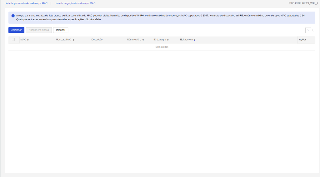
Adding a MAC address to the list
- Select the tab corresponding to the desired list:
- MAC address permit list (only devices in this list can connect to the network).
- MAC address deny list (devices in this list will be blocked and prevented from connecting).
- Click Add.
- In the Add MAC address modal, fill in the fields:
- MAC — The device's MAC address.
- MAC Mask — The corresponding mask (e.g.,
FFFF-FFFF-FFFFto specify exactly one host). - Description — Optional (1-128 characters).
- Click OK to save.
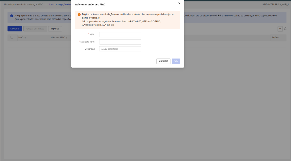
Deleting one or more MAC addresses
- To delete a single address, locate the corresponding record in the table and click Delete in the Actions column.
- To bulk delete, select the desired addresses by checking their checkboxes and click Bulk Delete.
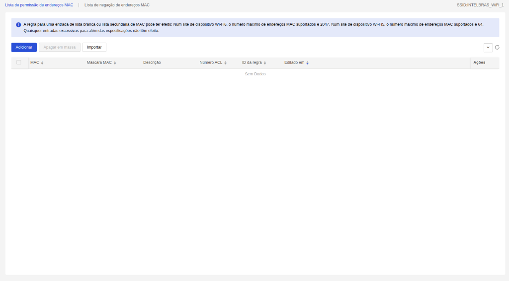
Configure access control per SSID
The Access Control feature lets you define network packet filtering rules for each SSID individually, controlling which IP addresses can send or receive traffic through the wireless interface.
Restrictions and guidelines
- This feature is supported only by AP firmware version 2586 or later.
- Rules are applied separately for Outgoing packets (sent traffic) and Incoming packets (received traffic).
- Each rule has a priority (0 to 65533); lower numbers mean higher evaluation priority.
Accessing Access Control
- Go to Network > Cloud APs > WLAN Settings > Wi-Fi Settings.
- Locate the desired SSID and click the Access Control icon.
- The Access Control page will open with two tabs: Outgoing packets and Incoming packets.
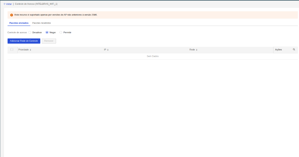
Setting the control mode
For each tab (Outgoing packets / Incoming packets), select the desired mode:
- Disable — Access control is off for this traffic direction. No rules are applied.
- Deny — Traffic from listed networks is blocked; all other traffic is allowed.
- Allow — Only traffic from listed networks is authorized; all other traffic is blocked.
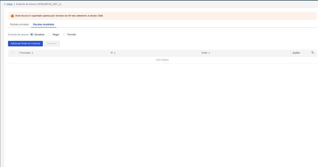
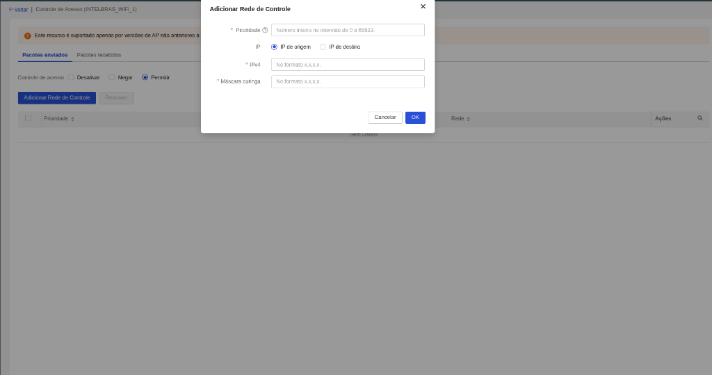
Adding a control network rule
- In the desired tab, select the Deny or Allow mode.
- Click Add Control Network.
- In the modal, fill in the fields:
- Priority — Integer between 0 and 65533. Lower values are evaluated first.
- IP — Select Source IP (device sending the packet) or Destination IP (target of the packet).
- IPv4 — Enter the IPv4 address in x.x.x.x format.
- Wildcard mask — Enter the wildcard mask in x.x.x.x format. Use 0.0.0.0 to specify a single host.
- Click OK to save the rule.
Removing a control network rule
- Select the rule(s) by checking the checkbox in the leftmost column.
- Click Remove.
Domain name whitelist and blacklist
The Domain name whitelist and blacklist feature allows you to control Wi-Fi client access to specific internet domain names directly in the INC Cloud Wi-Fi settings interface, without needing complex local firewall rules.
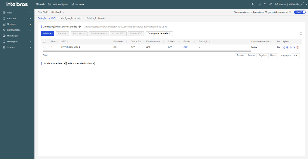
Important notice (Captive Portal requirement):
Both the Domain name whitelist and blacklist only take effect and operate when Captive Portal authentication is enabled for the wireless service (SSID) and a template has been created and configured. If Captive Portal authentication is not enabled or the template is not configured on the SSID, domain permission or blocking rules will not take effect.
Operation:
• Whitelist: Allows clients direct access to registered domains without going through the portal authentication screen.
• Blacklist: Prevents connected clients from accessing specified domains (exact operation depends on the AP model).
1. Domain name whitelist
What it is used for:
The Whitelist allows Wi-Fi clients to access only the domain names registered in the list, blocking all other internet addresses. It is widely used in networks with Captive Portals to grant free pre-authentication access to specific sites (for example: allowing access to corporate sites, external authentication servers, APIs, or payment gateways before the client logs into the portal).
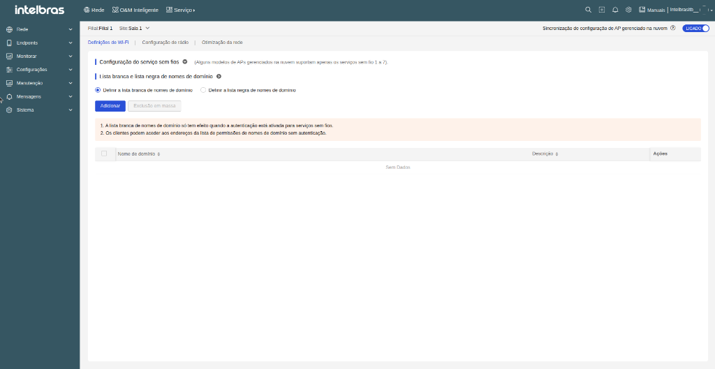
How to configure the Whitelist (Step-by-step):
- Go to Network > Cloud APs > WLAN Settings and click the Wi-Fi Settings tab.
- Below the SSID table, locate the Domain name whitelist and blacklist section.
- Select the Set domain name whitelist radio button.
- Click the Add button.
- In the displayed modal window (Add domain name to whitelist), fill in:
- Domain name: Enter the domain address (e.g., example.com). Accepts up to 253 characters (letters, numbers, hyphens -, underscores _, and dots .).
- Remarks: (Optional) Enter an explanatory note to identify the domain purpose (up to 100 characters).
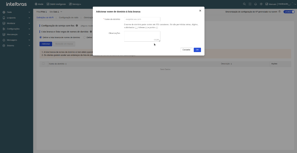
- Click OK to save the domain name to the whitelist.
How to remove domain names from the Whitelist:
- With the Set domain name whitelist option selected, check the checkbox next to the domain name to remove (or check the top box for bulk selection).
- Click the Bulk delete button or the Delete icon (trash can) in the Actions column.
- Confirm deletion by clicking OK.
2. Domain name blacklist
What it is used for:
The Blacklist is used to actively block client access to specific internet addresses registered in the list. It is recommended for prohibiting access to unwanted websites, social media, unauthorized streaming platforms, or malicious sites in corporate and public networks.
Blacklist guidelines:
1. How the domain name blacklist takes effect depends on the AP device model.
2. Connected clients are completely prevented from accessing domain blacklist addresses.
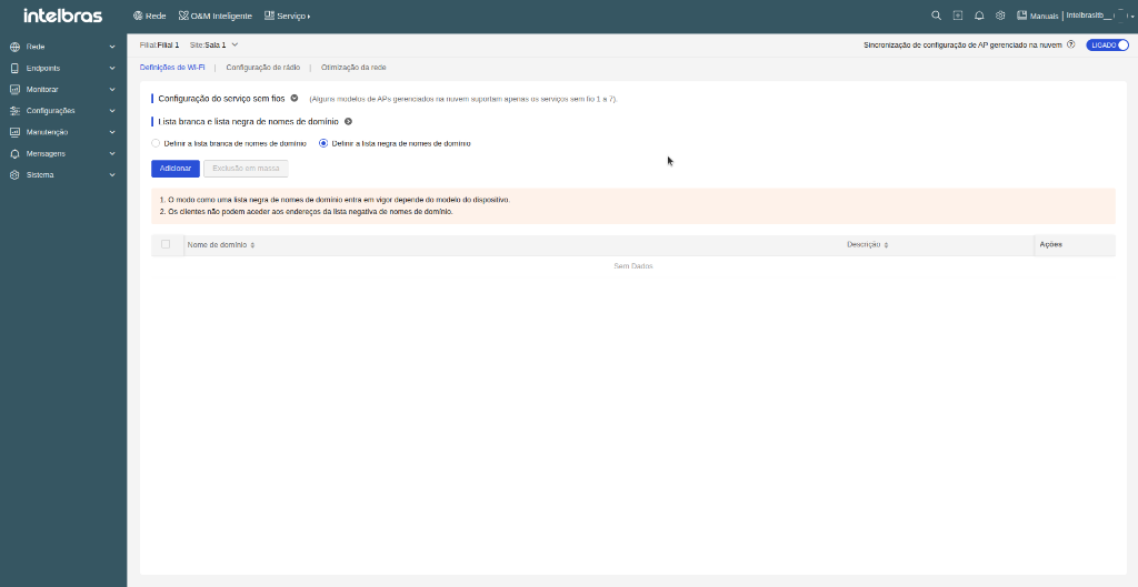
How to configure the Blacklist (Step-by-step):
- Go to Network > Cloud APs > WLAN Settings and click the Wi-Fi Settings tab.
- Below the SSID table, locate the Domain name whitelist and blacklist section.
- Select the Set domain name blacklist radio button.
- Click the Add button.
- In the displayed modal window (Add domain name to blacklist), fill in:
- Domain name: Enter the domain address to block (e.g., blockedwebsite.com). Accepts up to 253 characters (letters, numbers, hyphens -, underscores _, and dots .).
- Remarks: (Optional) Enter the reason for blocking or a description (up to 100 characters).
- Click OK to save and enable domain blocking.
How to remove domain names from the Blacklist:
- With the Set domain name blacklist option selected, check the checkbox next to the domain name to remove (or check the top box for bulk selection).
- Click the Bulk delete button or the Delete icon (trash can) in the Actions column.
- Confirm deletion.
Wireless QoS
The Wireless QoS (Bandwidth Limit) feature provides advanced traffic control and bandwidth management per SSID. When enabled on any SSID of a radio, the processing of QoS policies shifts to software forwarding to allow the application of the configured rules. As a consequence, the radio's maximum forwarding capability may be reduced compared to the standard hardware-accelerated operation. This behavior applies to the radio as a whole and can influence the performance of other SSIDs configured on the same radio. It is recommended to enable this feature only when bandwidth control is a deployment requirement.
Encryption service configuration
To synchronize SSID information, click Sync SSID Info.
Make sure you have created a Wireless service and configured the SSID information on the device.
Note: This feature is only available for ACs with versions prior to 5418 and routers with versions prior to 0809.
SSID information synchronization
To synchronize Wireless service settings on devices to INC Cloud, click Sync to Cloud. This operation synchronizes settings such as the Wireless service name, SSID, and guaranteed bandwidth rate to INC Cloud.
Note: This feature is only available for ACs with versions prior to 5418 and routers with versions prior to 0809.
Authentication and Captive Portal
This section provides comprehensive details on the operation and configuration of the INC Cloud authentication service, networking compatibility, device preparation, and the Captive Portal templates supported by the platform.
About INC Cloud Authentication
Intelbras INC Cloud provides abundant authentication methods for acces users such as employees, guests and IoT terminals. When a client wants to access the internet or the specific network resoucers, the access device redirects the client to the INC Cloud portal for authentication.
Note: The platform’s internal captive portal does not yet support the IPv6 protocol and is compatible only with the IPv4 standard. Therefore, for the feature to operate correctly, it is recommended to configure the authentication captive LAN to use only the IPv4 standard.
Intelbras INC Cloud offers the following benefits:
- No upper limit for authentication clients.
- Abundant authentication policies.
- Custom ads pushing services.
Intelbras INC Cloud provides the authentication methods listed in the Authentication methods table listed below:
| Authentication methods | Applicable scenarios | Remarks | Combined authentication |
|---|---|---|---|
| Fixed account | The network users are fixed, such as campus and office areas | Authentication based on username and password. The following functions are supported: LDAP, Import and export of accounts, Binding an account to multiple MAC addresses, Limit for concurrent clients. | Supported |
| Voucher authentication | Scenario with high operational and network requirements, such as hotels and clubs. | The network administrator pre-configures the vouchers for Internet access through INC Cloud. Only users with a voucher can connect to the network. | Supported |
| Google authentication | The network administrators use Google to collect information about the network users | The users must log in to Google to grant access to INC Cloud. This method is only available at https://inccloud.intelbras.com.br | Supported |
| Twitter authentication | The network administrators use Twitter to collect statistics about the network users. | The users must log in to Twitter to grant access to INC Cloud. This method is only available at https://inccloud.intelbras.com.br | Supported |
| Facebook authentication | The network administrators use Facebook to collect statistics about the network users. | The users must log in to Facebook to grant access to INC Cloud. This method is only available at https://inccloud.intelbras.com.br | Supported |
| One-Key authentication | Low requirements for operational and network statistics audit and collection, restaurants and stores. | MAC based authentication. The users can complete the authentication simply by clicking a button on the portal authentication page. | Supported |
| Hotel authentication | Hotels where users are allowed to access the network based on a data plan after passing identity authentication. An ISV is required for the interaction between the hotel and INC Cloud. | The users access the network by providing the hotel name and room number. | Supported |
| Email authentication | Scenarios that require users' email addresses. | Users access the network by providing an email verification code. | Supported |
| Dumb Terminal authentication | IoT devices, wireless printers and POS terminals. | Automated authentication for wireless terminals. | Not supported |
Authentication methods and network compatibility
| Authentication methods | Compatibility with networks with different authenticators | |
|---|---|---|
| ACs | Wireless Routers | |
| One-Key authentication | Yes | Yes |
| Fixed Account authentication | Yes | Yes |
| Facebook authentication | Yes | No |
| Voucher authentication | Yes | No |
| Hotel authentication | Yes | Yes |
| Email authentication | Yes | Yes |
| Combined authentication | Yes | Yes |
| Dumb Terminal authentication | Yes | Yes |
| Bulk authentication | Yes | Yes |
| Customized authentication page | Yes | Yes |
Note:
A Wireless router can act as an AC or fat AP to provide wireless authentication.
A wired router connects to the terminals directly or connects to the terminals
through a switch or a fat AP for authentication.
Configuration preparation
This section describes the network preparation steps, device configurations, and general settings in INC Cloud before creating and designing the portal.
Basic settings
Prerequisites
Before configuring INC Cloud authentication, complete the following tasks:
- Connect the device to INC Cloud. For more information, see the Intelbras INC Cloud Deployment Guide.
- Complete VLAN and DHCP settings.
- Configure Wireless services and ensure that the APs can go online.
Configure settings on the device
Restrictions and guidelines
Only software version 5405 or higher supports deploying authentication settings automatically. For other software versions, manually configure the following settings on the device.
For fast deployment of the following authentication methods, see Appendix A Authentication commands for the device.
- One-key authentication.
- Fixed account authentication.
- Facebook authentication.
- Dumb terminal authentication.
Configure general settings
1. Configure a portal authentication domain.
# Add an ISP domain named cloud and enter its view.
<Sysname> System-View
                        [Sysname] domain cloud
# Specify the authentication, authorization and accounting methods as none.
[Sysname-isp-cloud] authentication portal none
                        [Sysname-isp-cloud] authorization portal none
                        [Sysname-isp-cloud] accounting portal none
                        [Sysname-isp-cloud] quit
2. Configure cloud portal authentication.
# Add a portal Web server named cloud and specify its URL and type. (If the administrator configures the wireless service in INC Cloud, the configuration will be deployed to the device automatically.)
[portal web-server cloud
                        [Sysname-portal-websvr-cloud] url  http://inccloud-captive.intelbras.com.br/portal/protocol
                        [Sysname- portal-websvr-cloud] server-type oauth
# Configure a match rule to redirect HTTP requests that carry the user agent string CaptiveNetworkSupport to the URL http://inccloud-captive.intelbras.com.br/generate_404.
[Sysname-portal-websvr-cloud] if-match user-agent CaptiveNetworkSupport redirect-url http://oasisauth.intelbras.com/generate_404# Configure a match rule to redirect HTTP requests that carry the user agent string Dalvik/2.1.0(Linux;U;Android7.0;HUAWEI to the URL http://inccloud-captive.intelbras.com.br/generate_404.
[Sysname-portal-websvr-cloud] if-match user-agent Dalvik/2.1.0(Linux;U;Android7.0;HUAWEI redirect-url http://inccloud-captive.intelbras.com.br/generate_404# Configure a temporary pass rule to allow user packets that contain user agent information Mozilla to pass and then redirect the packets destined for the URL http://captive.apple.com to URL http://inccloud-captive.intelbras.com.br/portal/protocol.
[Sysname-portal-websvr-cloud] if-match original-url http://captive.apple.com user-agent Mo- zilla temp-pass redirect-url http://inccloud-captive.intelbras.com.br/portal/protocol# Configure a temporary pass rule to allow user packets that contain user agent information Mozilla to pass and then redirect the packets destined for the URL http://www.apple.com to URL http://inccloud-captive.intelbras.com.br/portal/protocol.
[Sysname-portal-websvr-cloud] if-match original-url http://www.apple.com user-agent Mozilla temp-pass redirect-url  http://inccloud-captive.intelbras.com.br/portal/protocol
                        [Sysname-portal-websvr-cloud] quit
# Configure a temporary pass rule to temporarily allow user packets that access URL http://10.168.168.168 to pass.
[portal web-server cloud
                        [Sysname-portal-websvr-cloud] if-match original-url http://10.168.168.168 temp-pass
# Enable the optimized captive-bypass feature for iOS users.
[Sysname-portal-websvr-cloud] captive-bypass ios optimize enable
                        [Sysname-portal-websvr-cloud] quit
# Enable direct portal authentication on service template Cloud.
[Sysname] wlan service-template Cloud
                        [Sysname-wlan-st-cloud] portal enable method direct
# Configure the authentication domain as cloud and specify portal Web server cloud as the portal Web server for portal authentication.
[Sysname-wlan-st-cloud] portal domain cloud
                        [Sysname- wlan-st-cloud] portal apply web-server cloud
                        [Sysname- wlan-st-cloud] quit
# Enable portal temporary pass and set the temporary pass period to 20 seconds.
[Sysname] wlan service-template Cloud
                        [Sysname-wlan-st-cloud] portal temp-pass period 20 enable
                        [Sysname-wlan-st-cloud] quit
# Add an HTTP-based local portal Web service and enter its view.
[Sysname] portal local-web-server http
                        [Sysname-portal-local-websvr-http] quit
# Add an HTTPS-based local portal Web service and enter its view.
[Sysname] portal local-web-server https
                        [Sysname] portal-local-websvr-https] quit
# Enable the HTTP and HTTPS services.
[Sysname] ip http enable
                        [Sysname] ip https enable
# Enable validity check on wireless portal clients.
[Sysname] portal host-check enable# Enable logging for portal user logins and logouts.
[Sysname] portal user log enable# Configure destination-based portal-free rule 1 to allow portal users to access the DNS service without authentication. (This example uses rule 114.114.114.114 255.255.255.255.)
[Sysname] portal free-rule 1 destination ip 114.114.114.114 255.255.255.255# Configure destination-based portal-free rules 2 and 4 to allow portal users to access the DNS service without authentication.
[Sysname] portal free-rule 2 destination ip any udp 53
                        [Sysname] portal free-rule 3 destination ip any tcp 53
                        [Sysname] portal free-rule 4 destination ip any tcp 5223
# Configure destination-based portal-free rule 5 to allow portal users to access the INC Cloud authentication server without authentication.
[Sysname] portal free-rule 5 destination oasisauth.intelbras.com# Configure destination-based portal-free rules 10 to 22 to allow portal users to access the INC Cloud authentication server without authentication.
[Sysname] portal free-rule 10 destination short.weixin.qq.com
                        [Sysname] portal free-rule 11 destination mp.weixin.qq.com
                        [Sysname] portal free-rule 12 destination long.weixin.qq.com
                        [Sysname] portal free-rule 13 destination dns.weixin.qq.com
                        [Sysname] portal free-rule 14 destination minorshort.weixin.qq.com
                        [Sysname] portal free-rule 15 destination extshort.weixin.qq.com
                        [Sysname] portal free-rule 16 destination szshort.weixin.qq.com
                        [Sysname] portal free-rule 17 destination szlong.weixin.qq.com
                        [Sysname] portal free-rule 18 destination szextshort.weixin.qq.com
                        [Sysname] portal free-rule 19 destination isdspeed.qq.com
                        [Sysname] portal free-rule 20 destination wx.qlogo.cn
                        [Sysname] portal free-rule 21 destination wifi.weixin.qq.com
                        [Sysname] portal free-rule 22 destination open.weixin.qq.com
# Enable portal safe-redirect.
[Sysname] portal safe-redirect enable# Specify HTTP request methods permitted by portal safe-redirect.
[Sysname] portal safe-redirect method get post# Specify browser types permitted by portal safe-redirect.
[Sysname] portal safe-redirect user-agent Android
                        [Sysname] portal safe-redirect user-agent CFNetwork
                        [Sysname] portal safe-redirect user-agent CaptiveNetworkSupport
                        [Sysname] portal safe-redirect user-agent MicroMessenger
                        [Sysname] portal safe-redirect user-agent Mozilla
                        [Sysname] portal safe-redirect user-agent iPhone
                        [Sysname] portal safe-redirect user-agent micromessenger
External RADIUS Server Configuration and 802.1X Authentication
INC Cloud allows integration with external RADIUS servers for centralized and secure authentication of wireless clients using the 802.1X (WPA/WPA2/WPA3 Enterprise) standard. This feature is ideal for corporate networks requiring individual user credential validation against existing AAA (Authentication, Authorization, and Accounting) external servers in the infrastructure.
The deployment of the external RADIUS service in INC Cloud is carried out in two main steps:
- RADIUS Scheme Registration: Registering a profile containing the IP addresses of authentication and accounting servers, UDP ports, shared secrets, ISP domain name, and protocol timers.
- Applying to SSID: Linking the created RADIUS Scheme to wireless networks (SSIDs) via the advanced settings menu with 802.1X encryption enabled.
Configure External RADIUS Scheme
The RADIUS Scheme centrally stores connection parameters to primary and secondary (redundancy) authentication and accounting servers, as well as ISP domain definitions and rules for username formatting before sending requests to the server.
Procedure to register a new RADIUS Scheme:
- Navigate to the Authentication screen using the left side menu:
Go to Network > Settings > Cloud APs > Authentication (or via the top header menu in Network > Authentication > Authentication).

- On the Authentication screen, click the RADIUS Server tab.
- In the RADIUS Scheme block, click the Add button to register a new authentication RADIUS server already created and active on your network.
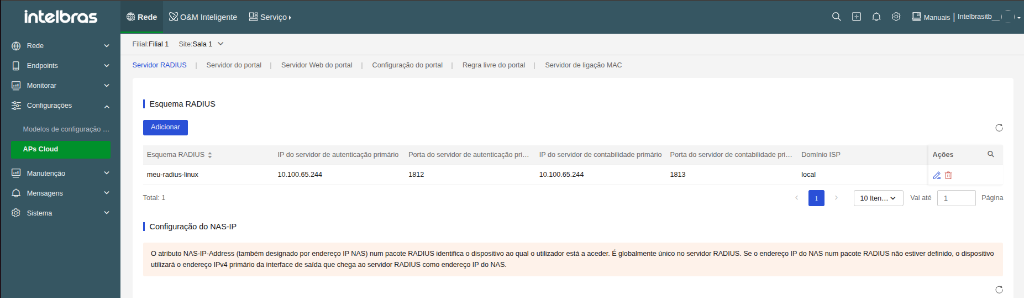
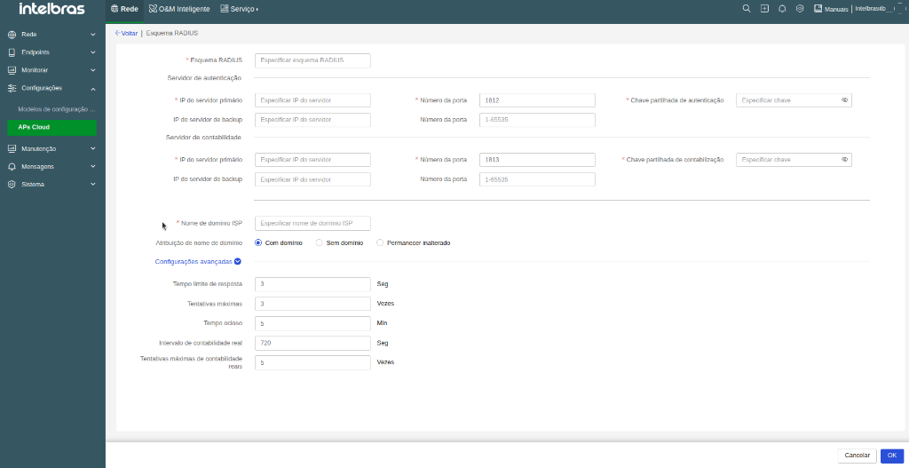
- On the RADIUS Scheme form window (Back | RADIUS Scheme), fill in the server details:
- RADIUS Scheme: Enter a unique identification name for the RADIUS profile (e.g.,
corp-radius). - Authentication server:
- * Primary server IP: Enter the IPv4 address of the primary RADIUS authentication server (e.g.,
10.100.65.244). - * Port number: Enter the listening UDP port of the server (default:
1812). - * Authentication shared key: Enter the shared secret registered on the RADIUS server.
- Backup server IP / Port: (Optional) Enter the IP and port (range
1 to 65535) of the secondary server for failover.
- * Primary server IP: Enter the IPv4 address of the primary RADIUS authentication server (e.g.,
- Accounting server:
- * Primary server IP: Enter the IPv4 address of the accounting RADIUS server.
- * Port number: Enter the accounting UDP port (default:
1813). - * Accounting shared key: Enter the shared secret for accounting services.
- Backup server IP / Port: (Optional) Enter the IP and port of the secondary accounting server.
- ISP Domain Settings:
- * ISP domain name: Define the name of the logical group (the domain) responsible for processing access requests for this SSID (e.g.,
localorcloud). - Domain name assignment: Defines how the Access Point handles the username string before sending it to the RADIUS server (crucial if a user tries logging in with a domain suffix like
user@company.com):- With domain: The AP appends or forces sending the login including the configured ISP domain name to the server (e.g.,
user@local). - Without domain: The AP strips any domain suffix (the
@company.com) and sends only the plain username (e.g.,user) for server validation. - Remain unchanged: The AP leaves the string unmodified and forwards to the authentication server exactly the text typed by the client at login.
- With domain: The AP appends or forces sending the login including the configured ISP domain name to the server (e.g.,
- * ISP domain name: Define the name of the logical group (the domain) responsible for processing access requests for this SSID (e.g.,
- RADIUS Scheme: Enter a unique identification name for the RADIUS profile (e.g.,
- (Optional) Click Advanced settings to expand timer options (Response timeout, Maximum retries, Idle timeout, and Real-time accounting interval).
- Click OK in the bottom right corner to save and register the RADIUS Scheme.
Technical Concept: ISP Domain Structure
In the Intelbras ecosystem, an ISP domain is a logical structure where the device defines which authentication, authorization, and accounting (AAA) methods apply to network users. Choosing the Domain name assignment setting determines whether a client login attempt might be rejected if the user enters a format incompatible with the user database registered on the RADIUS server (or under the 802.1X user tab).
NAS-IP Configuration
Below the registered RADIUS Schemes table, the descriptive NAS-IP Configuration block is displayed:
The NAS-IP-Address attribute in a RADIUS packet identifies the access device (AP/AC) requesting client authentication. It is unique on the RADIUS server. If the NAS IP address is not manually defined in the device settings, the equipment will automatically use the primary IPv4 address of the outgoing interface that reaches the RADIUS server.
Apply RADIUS Authentication to SSID
After registering the RADIUS Scheme, the next step is to apply it to the desired wireless network (SSID) to enable 802.1X access control on Wi-Fi.
Procedure to apply RADIUS to an SSID:
- In the left side menu, navigate to Settings > Cloud APs > WLAN Settings (or Network > WLAN Settings in the header) and select the Wi-Fi Settings tab.
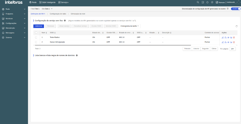
- Create a new SSID by clicking Add or locate an existing SSID and, in the Actions column, click the Edit icon (pencil).
- In the SSID configuration window, locate the Advanced settings section and configure the security fields:
- In the Encryption field, turn on 802.1X.
- In the Configure AAA field, select External server.
- In the dropdown menu under External server, select the added RADIUS scheme (e.g.,
corp-radius). - In the Security mode field, select the desired policy (e.g., WPA / WPA2-Compliant).
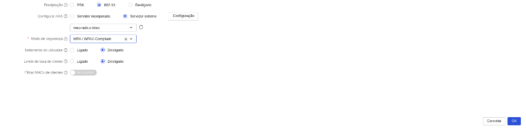
- Click OK in the bottom right corner to save and apply settings to the SSID.
Summary of Security Parameters on SSID
| Parameter | Description and Functionality |
|---|---|
| Encryption | Turn on 802.1X to activate corporate authentication. |
| Configure AAA | Select External server to use a remote RADIUS server registered in the system. (If needed, the Configuration button opens the scheme registration window directly). |
| Select RADIUS server | Open the dropdown menu and select the previously added RADIUS Scheme. |
| Security mode | Select the network encryption policy (e.g., WPA / WPA2-Compliant or WPA3 Enterprise). |
Important (Network and Firewall Requirements): Make sure Access Points and the RADIUS server have direct IP network connectivity. Verify that UDP ports 1812 (Authentication) and 1813 (Accounting) are allowed through any firewalls in your infrastructure.
Creation and Design of the Captive Portal
This section explains how to create Captive Portal templates, access the graphic editor, and design the authentication pages for your clients. INC Cloud offers two routes to create a Captive Portal template, each suited for a different purpose:
- Via the Service menu — You create a centralized, standalone template that is saved to the system library. This template can be linked to one or more SSIDs at any time, making it ideal for networks with multiple access points that should display the same portal. To edit the template in the future, you must return to the Portal Authentication screen — it is not possible to edit the template directly through the SSID settings when it was created and linked via this route.
- Directly on the SSID — You enable authentication within a specific SSID's settings. The template is created and bound exclusively to that network, making it the fastest option when you only need to configure a single access point.
In both cases, the Captive Portal graphic editor is the same and you will have access to all available authentication methods.
Create template via the Service menu (Recommended for global creation)
Use this route when you need a reusable template that can be linked to multiple SSIDs. The created template will be available in the system's centralized library for use across any network configured in INC Cloud. Follow the steps below to create and name the template:
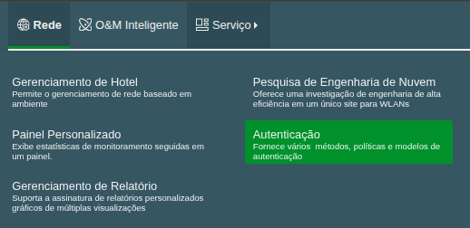
- On the top header, select the menu Service > Authentication.
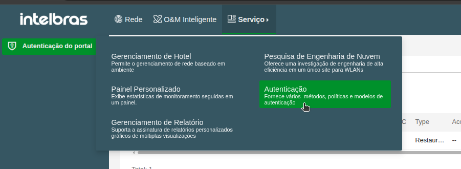
- You will be redirected to the Portal Authentication screen, which is the centralized library where all Captive Portal templates created in the account are stored. This is also the screen you return to whenever you want to edit an existing template — simply click the edit icon next to it. To create a new template, click Add.
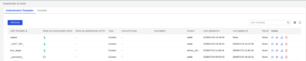
- Choose one of the available design templates and click Select (templates are fully editable).
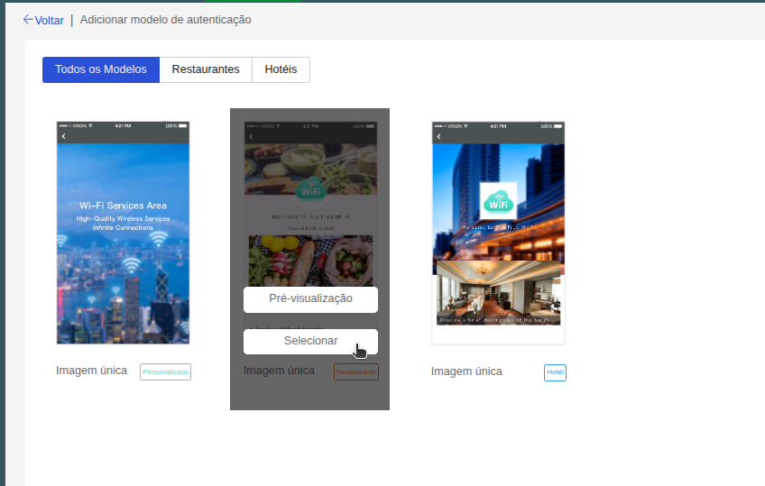
- Enter an identification name for your template and click Apply.
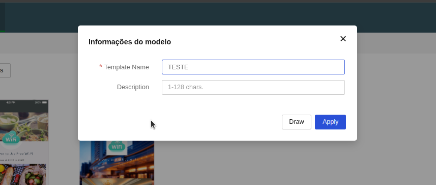
- Click OK to confirm and open the Captive Portal editor screen.
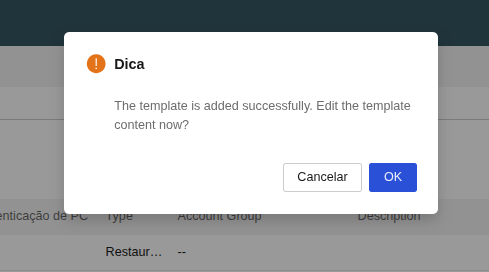
The Captive Portal graphic editor will open automatically. In it, you can configure and visually customize the authentication portal to your needs — including logo, background images, authentication method, text, colors, and much more.
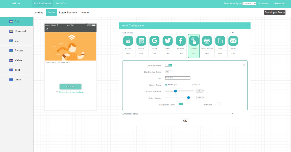
Detailed configuration steps for each authentication method are available below. Select the method you wish to use:
- One-Key Authentication
- Fixed Account Authentication
- DNS Prerequisites (Google Auth)
- Google Authentication
- Twitter Authentication
- Voucher Authentication
- Hotel Authentication
- Email Authentication
Important: When a template is linked to an SSID via this route, it cannot be edited directly through that SSID's settings. All future edits must be made by navigating to Service > Authentication and clicking the edit icon of the corresponding template. For more details, see the Edit Captive Portal template section.
Create template directly on the SSID (Quick setup)
Use this route when you want to configure the Captive Portal for a single SSID quickly. By enabling authentication directly in the wireless network profile, the created template is bound exclusively to that SSID — no need to access the Service menu or perform a separate linking step afterward. Follow the steps below:
- Go to Network > Cloud APs > WLAN Settings > Wi-Fi Settings.
- Click Add to create a new SSID or click the Edit icon (pencil) to modify an existing one.
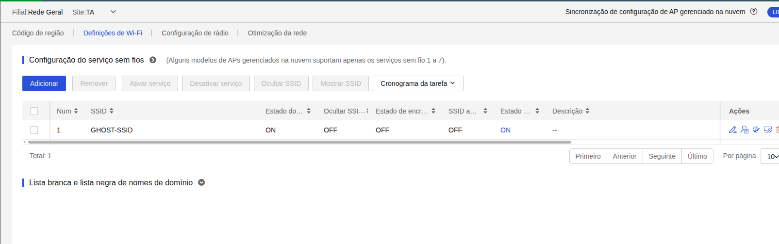
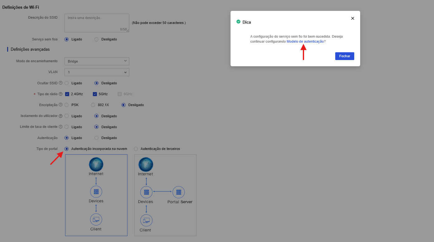
- In the SSID configuration window, locate the Advanced settings section and enable the Authentication field (select On).
- In the Portal type field, select Cloud-integrated authentication.
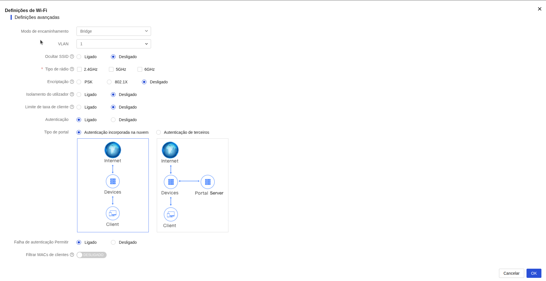
- Click OK. A confirmation message will be displayed asking if you want to continue configuring the Authentication template.
- Click Authentication template to go directly to the template creation and drawing screen, where you can perform the authentication settings.
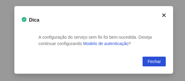
Next step: After accessing the template creation and drawing screen, the configuration and visual customization of the page depend on the chosen authentication method (such as One-Key, Voucher, SMS, Facebook, etc.). Go to the Captive portal design section to see the detailed step-by-step on how to configure and draw the capture page according to your needs.
Tip: If you closed the confirmation window without clicking Authentication template, you can access the drawing screen at any time. To do this, go back to Wi-Fi Settings, locate the SSID and click the Draw icon in the Actions column.
Important: If the SSID is using a template that was created and linked via the Service > Authentication menu, you will not be able to edit the template settings or design directly through the SSID profile or the draw icon. In these cases, editing the portal must be done via the centralized library under the Service > Authentication menu.
After opening the graphic editor through any of the routes above, select the authentication method you wish to configure below to view detailed design and parameter instructions:
- One-Key authentication
- Fixed Account authentication
- DNS Prerequisites (Google Auth)
- Google authentication
- Twitter authentication
- Voucher authentication
- Hotel authentication
- Email authentication
- Facebook authentication
- Combined authentication
- Dumb terminal authentication
- Bulk authentication
Configure One-Key authentication
One-Key authentication allows users to access the Wi-Fi network with just one click, without the need to fill out forms or enter credentials. It is the fastest and simplest solution for free access networks.
Drawing and Parameter Settings
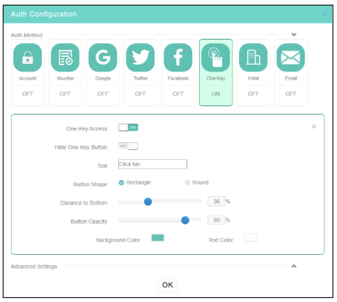
- In the Captive Portal editor, click the One-Key box in the Auth Configuration area.
- Enable the one-key authentication and confirm it. Configure other session settings as needed.
- Click OK or Release in the upper right corner of the page to save the template.
After configuring all parameters and completing the portal design for this authentication method, it will not be active on your network yet. For clients to start being directed to your captive portal, it is necessary to complete the final step of linking the generated template to the desired SSID. Please refer to the detailed step-by-step guides in the Direct Creation and Linking on SSID or Linking Template via Service menu sections.
Configure Fixed Account authentication
Fixed Account authentication requires the user to enter a predefined username and password to gain network access. It is ideal for secure connections for employees or recurring users.
Fixed Account authentication allows network access via a username and password. The way these accounts are created depends on how the administrator configures the portal.
Restrictions and guidelines
- If you do not configure the validity period or configure it as 0, the account never expires.
- If you select Bind MAC Address and do not enter any MAC addresses, clients that use the fixed MAC address might be excluded.
- The account is not limited.
- If you select Sent by Email, the system sends the account name and password to the specified email address. The number of email addresses cannot exceed 10 and must be separated by commas.
1. Drawing and Parameter Settings
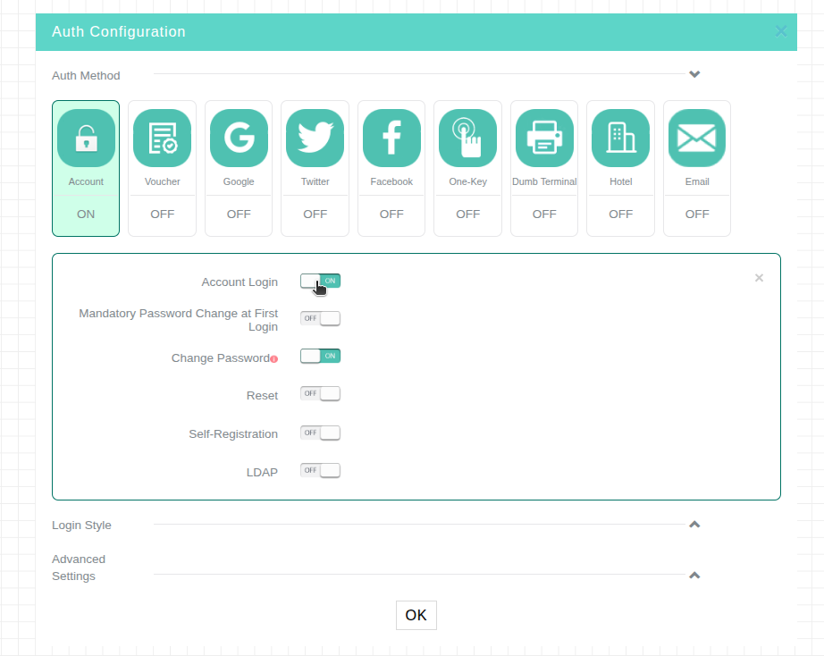
- In the Captive Portal editor, in the Auth Method row, select the Account option and enable the configuration.
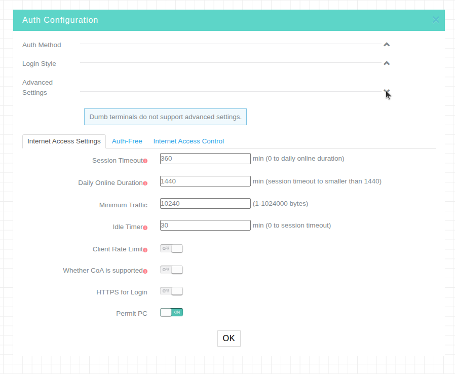
- In Advanced Settings, configure the session and idle time settings as needed.
- After configuring these settings, click OK to save the template.
2. Fixed Account Generation for Authentication
- On the top navigation bar, select Settings > Cloud APs > Users.
- Select a branch and a site at the top of the page.
- Click the Portal Users tab and then click the Fixed Accounts tab.
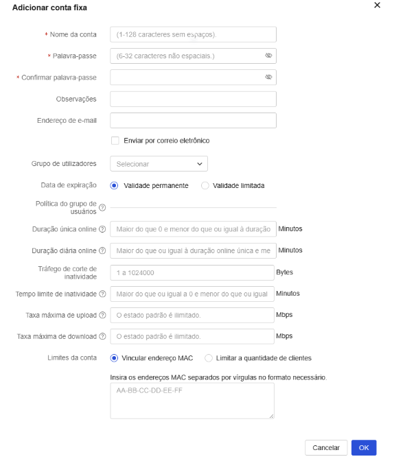
- Click Add.
- Configure fixed account information as required and click OK.
Self-Registration
By default, fixed account access management is handled by the network administrator, who is responsible for creating credentials (username and password) in the system and delivering them to users. With this option enabled, users can register themselves on the network without administrator intervention. When self-registration is enabled, the Required Registration Info options appear. Select the information you want users to provide when registering on the network.
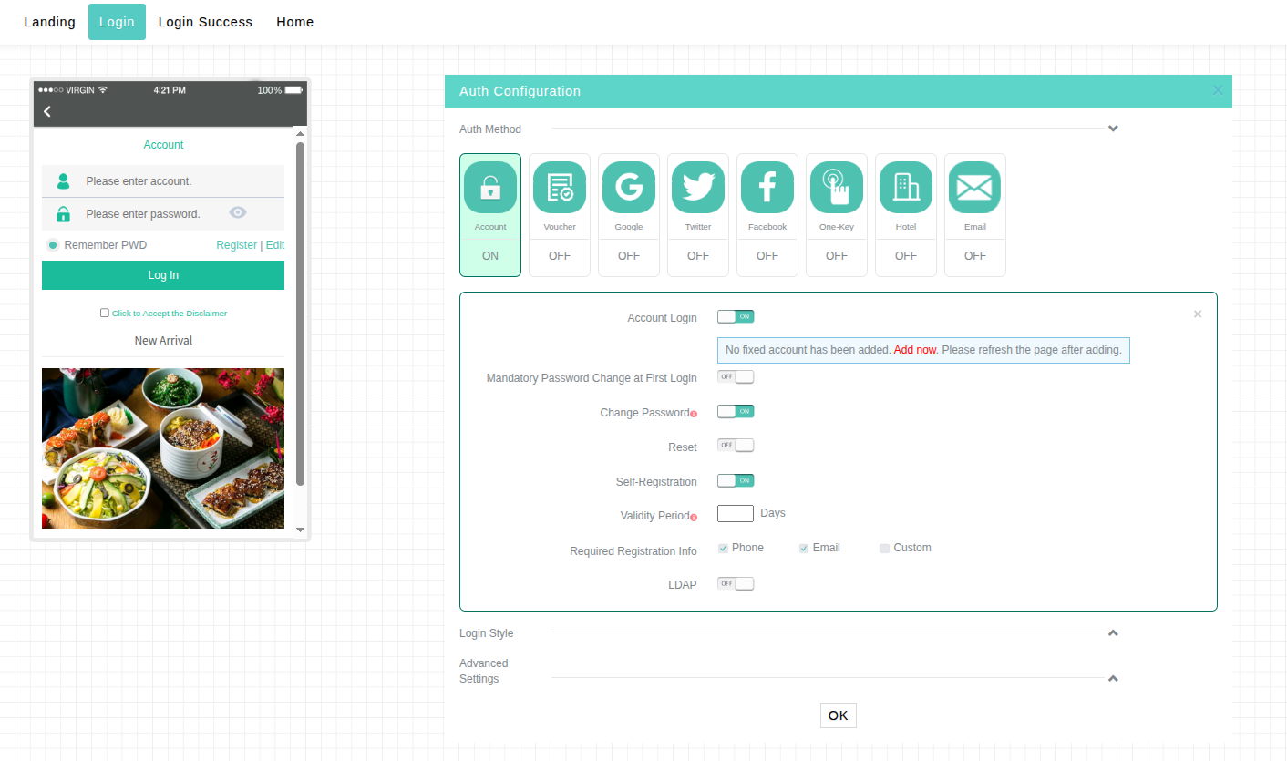
Custom field: When you select this option, you can create a free-form field to request additional information during registration, such as a tax ID or employee number.
The Custom field is available exclusively when editing the template linked to the SSID. To access it, navigate to: Network > Cloud APs > WLAN Settings > Wi-Fi Settings.
If the SSID already exists and authentication is enabled, click the Draw icon (color palette) in the corresponding Actions column to open the authentication template.
Otherwise, click Add to create a new SSID, go to Advanced settings > Authentication: Enabled > Portal type: Cloud-integrated authentication, and upon saving click to configure the Authentication template.
On the template editing screen, the Custom field will be available in the Required Registration Info options of the template linked to that SSID.
Important: If you create the template using the Service > Authentication method and link it to the SSID later (as described in Linking Template via Service menu), the Custom field will not be available in the registration info menu. The Custom field can only be enabled and configured if the template is created directly in the SSID profile, using the Direct Creation and Linking on SSID method.
Data entered in this field is not validated by the system. The portal only requires that the field not be left blank, but does not verify the authenticity or format of the information. For example, if the field is intended to capture a tax ID, the user will be able to complete registration even if they type letters or an invalid number sequence.
Next Step: Linking to the SSID
After configuring all parameters and completing the portal design for this authentication method, it will not be active on your network yet. For clients to start being directed to your captive portal, it is necessary to complete the final step of linking the generated template to the desired SSID. Please refer to the detailed step-by-step guides in the Direct Creation and Linking on SSID or Linking Template via Service menu sections.
DNS and Local Infrastructure Prerequisites (Google Authentication)
To ensure Google authentication works correctly, make sure to apply the following pre-configurations to the AP via CLI:
1. VLAN and VLAN Interface Creation
Create the visitor VLAN (e.g., VLAN 10) and configure its corresponding VLAN interface with the IP address that will serve as the local gateway:
# Create the visitor VLAN:
vlan 10

# Access the VLAN interface and define the IP address and subnet mask:
interface Vlan-interface 10
 ip address 192.168.x.1 255.255.255.0
2. DHCP Server Configuration (DNS Pointing to the AP)
The DHCP server of the visitor network must deliver the IP address of the AP's own local VLAN interface as the primary DNS server (using the dns-list parameter). Do not configure public external DNS servers (such as 8.8.8.8) directly in the clients' DHCP server.
# Example DHCP pool configuration for the visitor VLAN (e.g., VLAN 10):
dhcp server ip-pool vlan10
 gateway-list 192.168.x.1
 network 192.168.x.0 mask 255.255.255.0
 dns-list 192.168.x.1  <-- IMPORTANT: Point to the AP's local IP (Gateway)
 expired day 0 hour 1
3. Enabling DNS Proxy and Host Mapping on the AP
Enable the DNS Proxy feature on the Access Point so it can safely process and forward client requests. It is also recommended to statically map the hosts for Google authentication services:
# Enable DNS proxy and define the external DNS servers the AP will consult:
dns proxy enable
dns server 8.8.8.8
dns server 114.114.114.114

# Register Google's static host with an extended aging time to prevent network resolution failures:
ip host accounts.google.com 142.251.0.84
dns host accounts.google.com aging-time 4320
4. Local NAT and Routing Configuration
To ensure visitors have a routing path to the internet before and after authentication, make sure the uplink interface (e.g., Vlan-interface 1) is configured with NAT outbound:
# Create basic ACL to permit traffic from the visitor subnet:
acl basic 2000
 rule 0 permit source 192.168.x.0 0.0.0.255

# Apply NAT to the AP's WAN/Uplink interface:
interface Vlan-interface 1
 nat outbound 2000
5. Essential Portal Free Rules (Walled Garden)
Add the following traffic bypass rules (Free Rules) to allow the mandatory communication flow with the cloud and Google login servers before the user is authenticated:
portal free-rule 20029 destination test-inccloud.intelbras.com.br
portal free-rule 20030 destination oauth2.googleapis.com
portal free-rule 20031 destination apis.google.com
portal free-rule 20033 destination ogs.google.com
portal free-rule 20034 destination myaccount.google.com
portal free-rule 20038 destination googleusercontent.com
Configure Google authentication
Google authentication allows visitors to connect to the Wi-Fi network using their Google account credentials. To enable this integration, it is necessary to previously create an OAuth project in the Google Developer Console.
Creating a Google app
1. Log in to the Google Cloud Platform at https://console.cloud.google.com/apis.
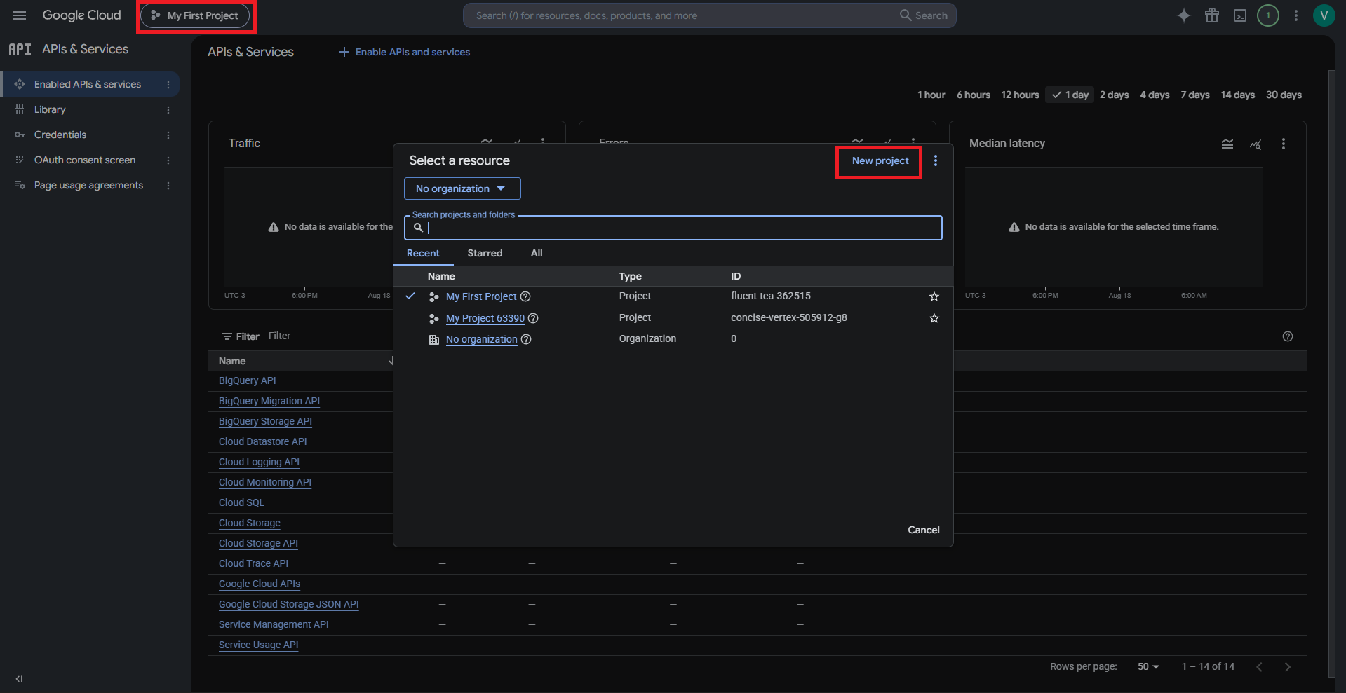
2. Click the project selector at the top of the page (e.g., My First Project) and then click New project.
Project creation
3. Set the basic project settings and click Create.
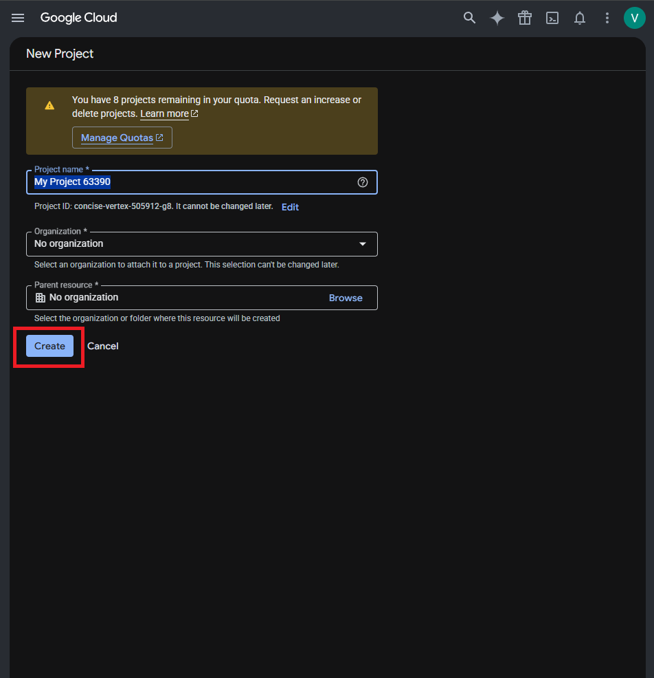
Basic settings of the project
4. Configure the OAuth consent screen settings.
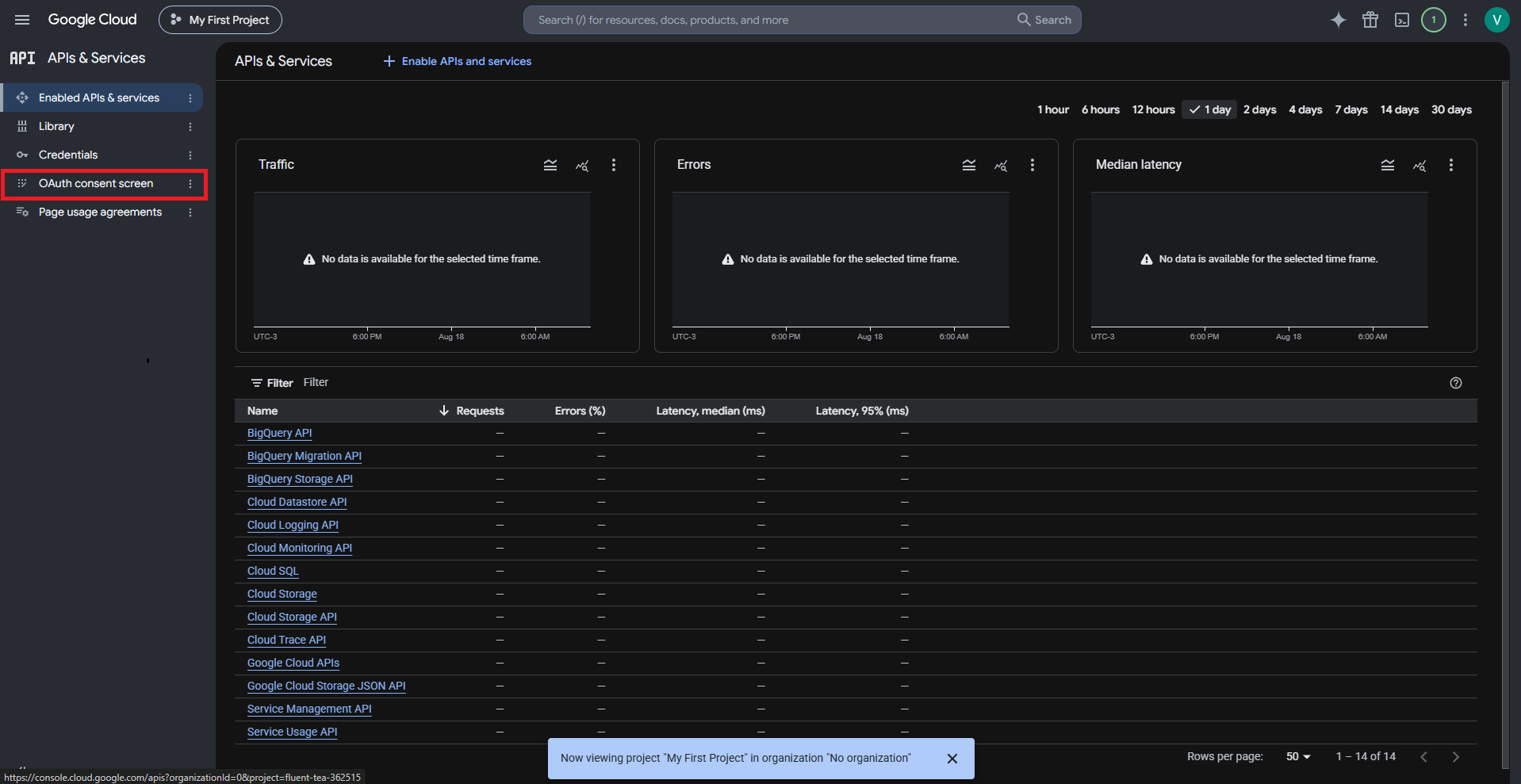
Entering the OAuth consent screen
- Select External as the user type on the audience screen.
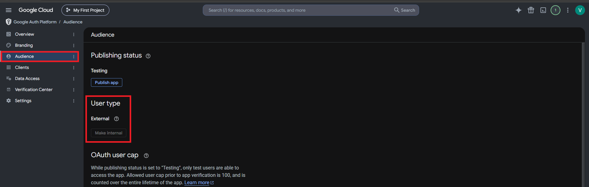
Selecting a user type
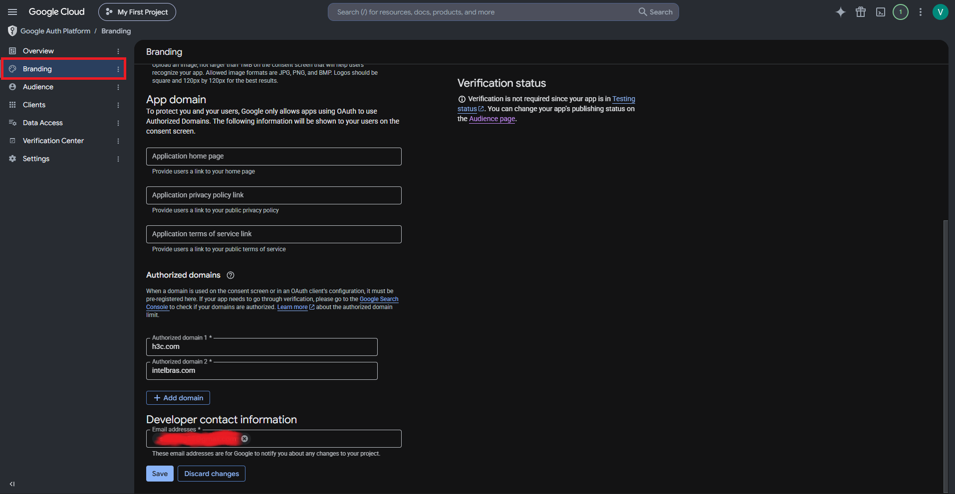
- Edit app registration settings. Go to the branding tab.
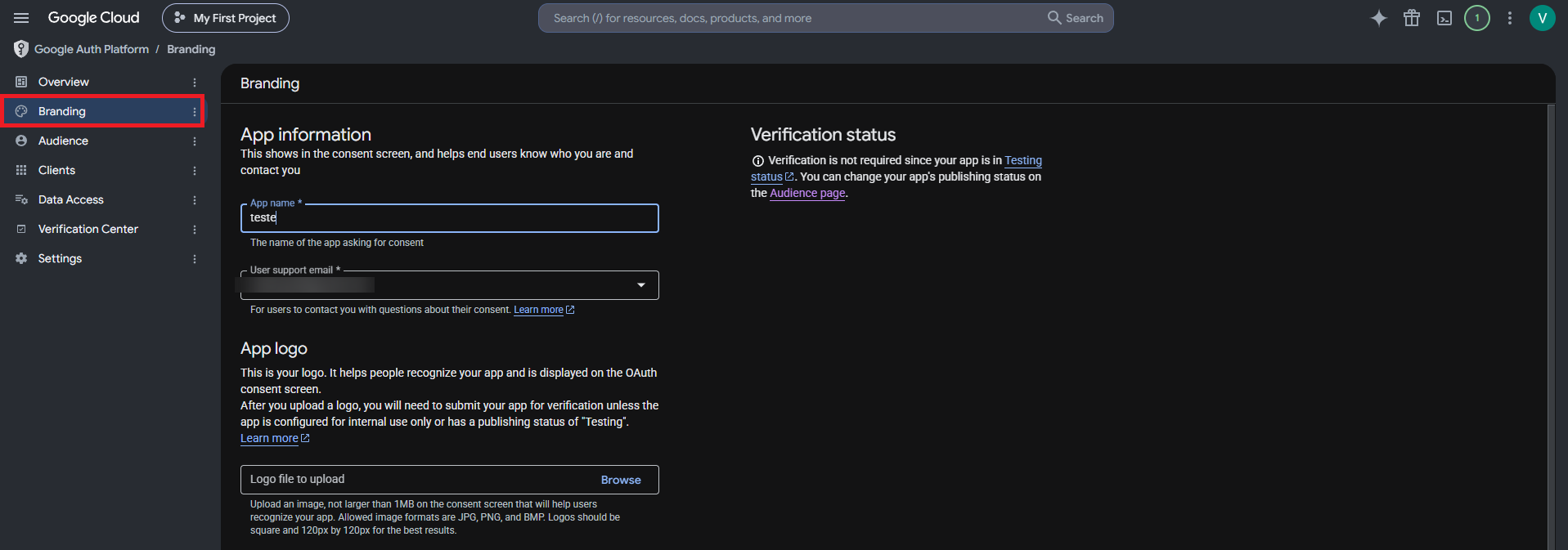
Editing app registration settings
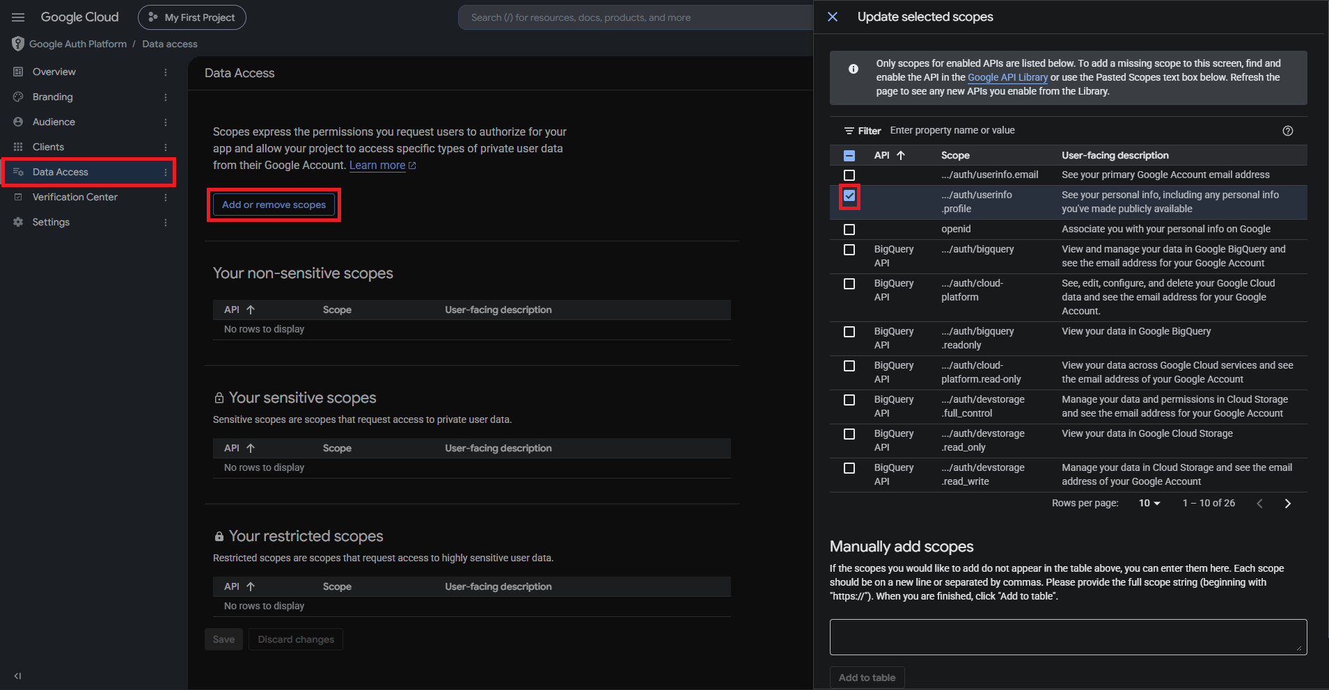
- Configure scopes. You only need to select userinfo.profile.
Updating scopes
- Configure test users. Click Add Users to add test users. Only test users can log in to a Google app in the Testing state.
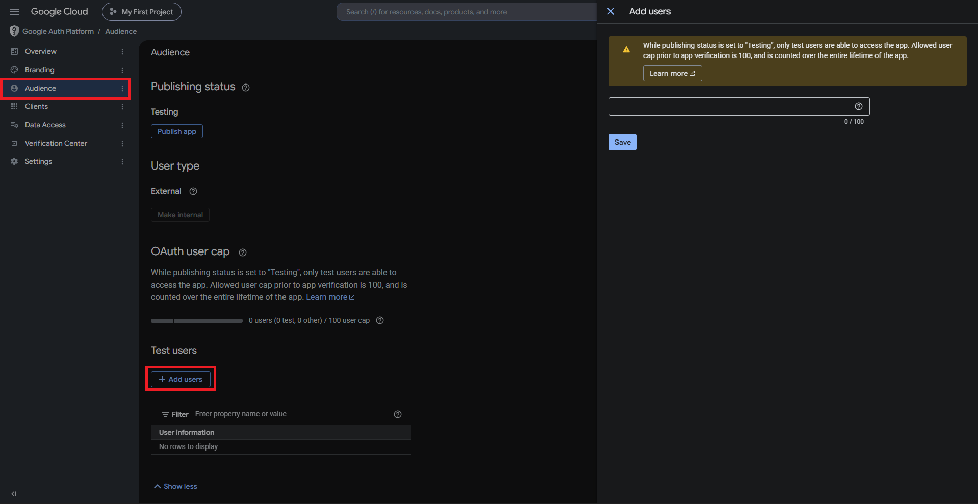
Adding test users
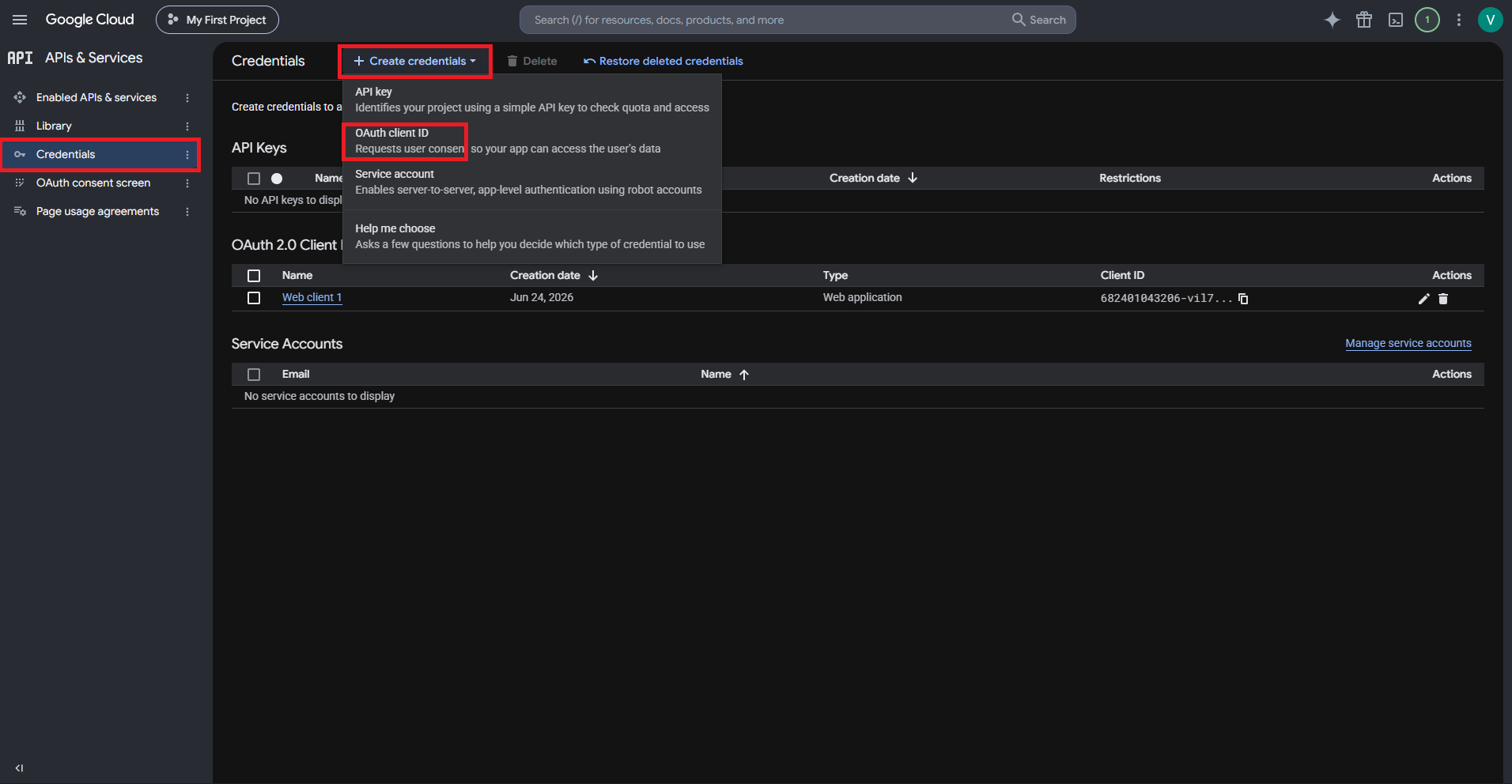
- Create credentials. Click CREATE CREDENTIALS and then click OAuth client ID.
- Select Web application as the application type.
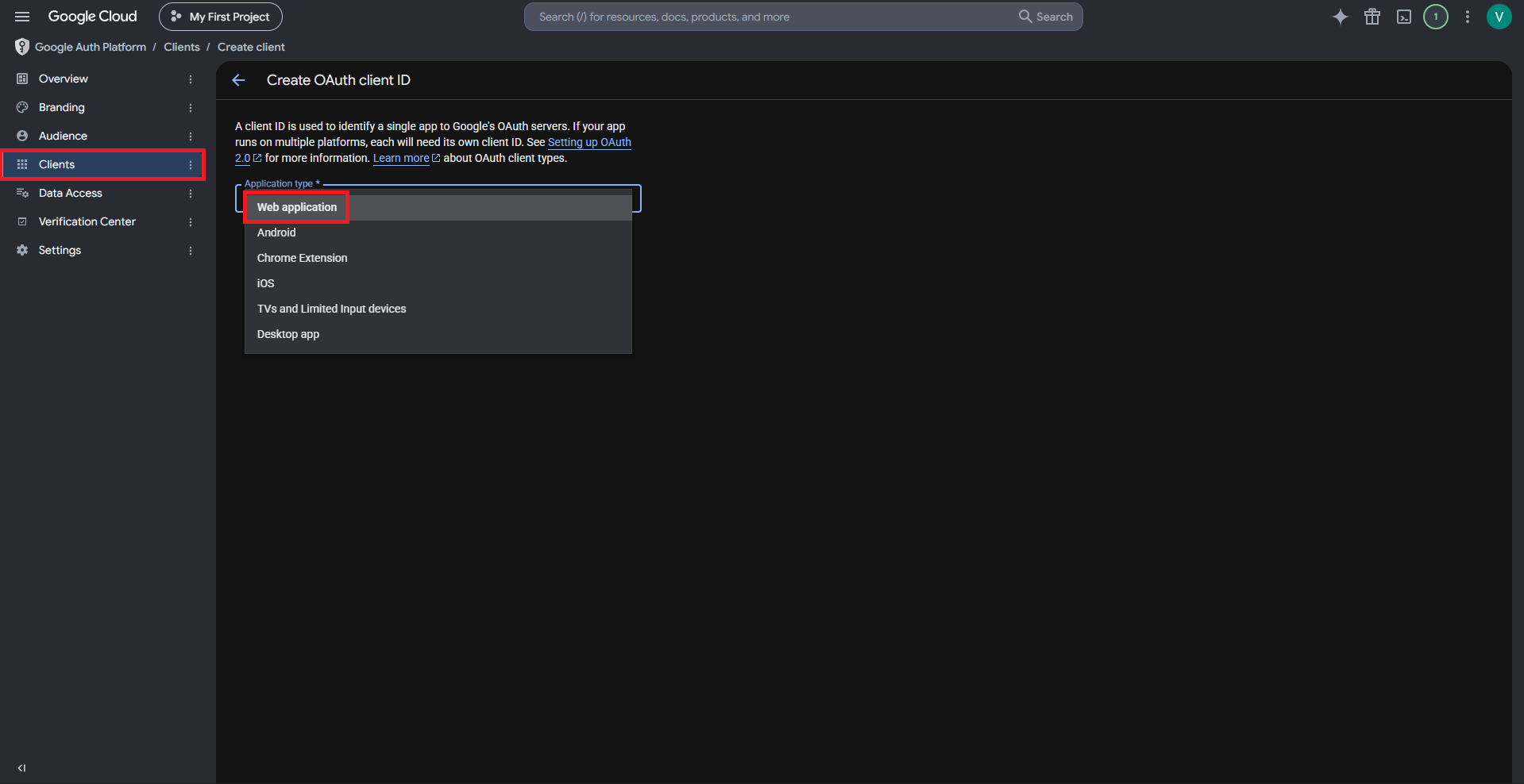
Selecting an application type
- Add authorized JavaScript origins and authorized redirect URLs. The authorized redirect URI is https://inccloud-captive.intelbras.com.br/portal/googleCallback.html. The specified JavaScript origins must start with https.
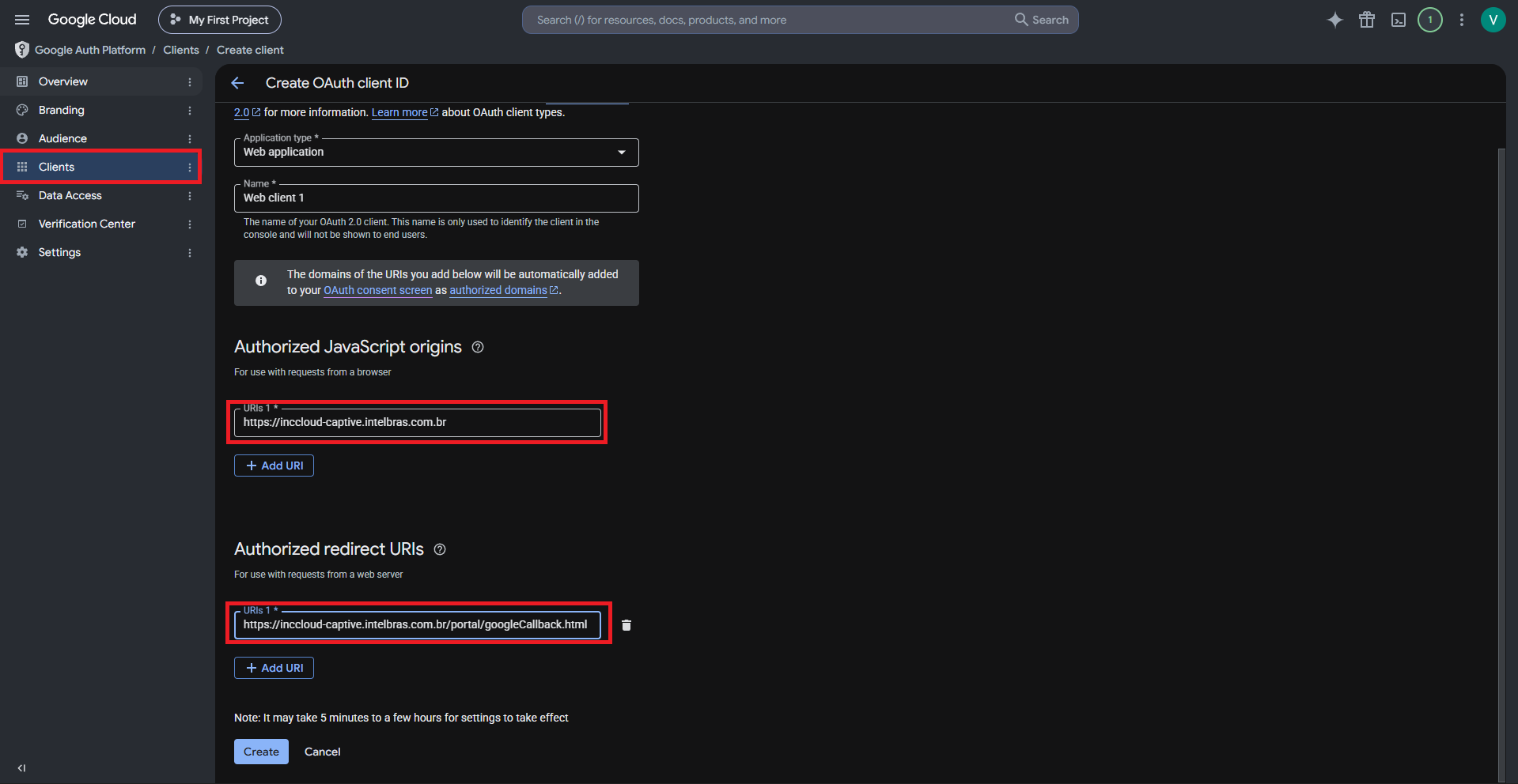
Authorized JavaScript origins and authorized redirect URIs
5. Once the credential is created, click Credentials in the left navigation panel. In the list that opens, click Edit OAuth client in the Actions column of the OAuth 2.0 Client IDs row. On the page that opens, you can view the client ID and client secret.
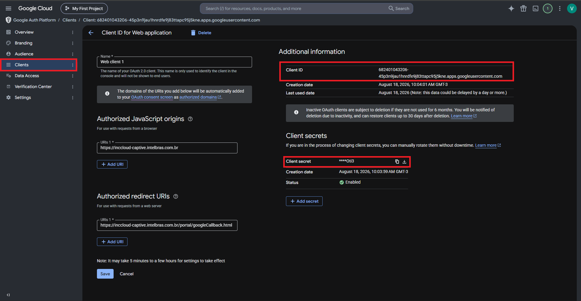
Client information
Drawing and Parameter Settings
- In the Captive Portal editor, click the Google box in the Auth Configuration area and enable Google authentication.
- Enter the client ID and client secret, and configure other settings as needed.
- Click OK and then click Release in the upper right corner of the page to save.
Google authentication can be used in combination with:
- Fixed Account authentication.
- Member authentication.
- Facebook authentication.
- Twitter authentication.
You can use up to three authentication methods simultaneously.
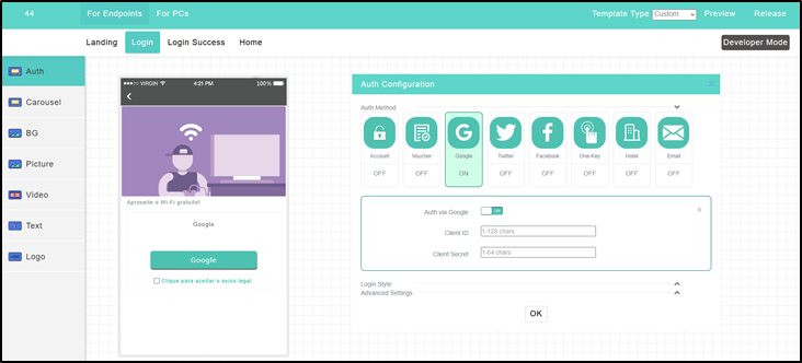
Google authentication
After configuring all parameters and completing the portal design for this authentication method, it will not be active on your network yet. For clients to start being directed to your captive portal, it is necessary to complete the final step of linking the generated template to the desired SSID. Please refer to the detailed step-by-step guides in the Direct Creation and Linking on SSID or Linking Template via Service menu sections.
Configure Twitter authentication
Twitter authentication allows users to authenticate to the network using their Twitter credentials. This method requires previously creating an app on the Twitter Developer Platform.
Creating a Twitter app
- Log in to the Twitter Developer Platform at https://developer.twitter.com.
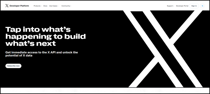
Home page
- Register for a developer account and accept terms. The API account is created by default. Then change the following settings.
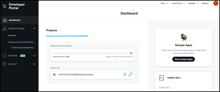
Dashboard with created account
- Record the API key and API key secret. They will be used later.
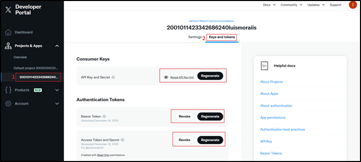
Passwords
- Configure app settings. Click App settings in the Apps area.
- Click Set up in the User authentication settings area.
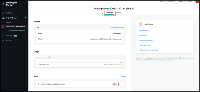
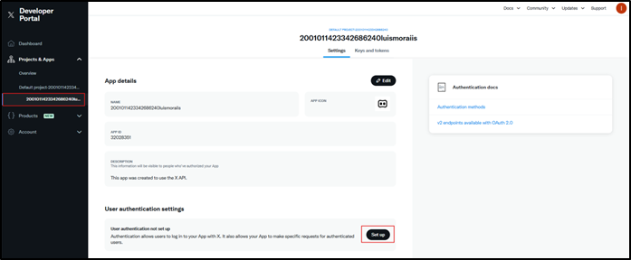
User authentication settings
- Enable OAuth 1.0a.
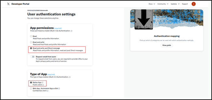
OAuth 1.0a enablement
- Specify a redirect URL and a website URL.
- Redirect URL: https://inccloud-captive.intelbras.com.br/portal/twitterCallback.html.
- Website URL: enter a URL in domain name format.
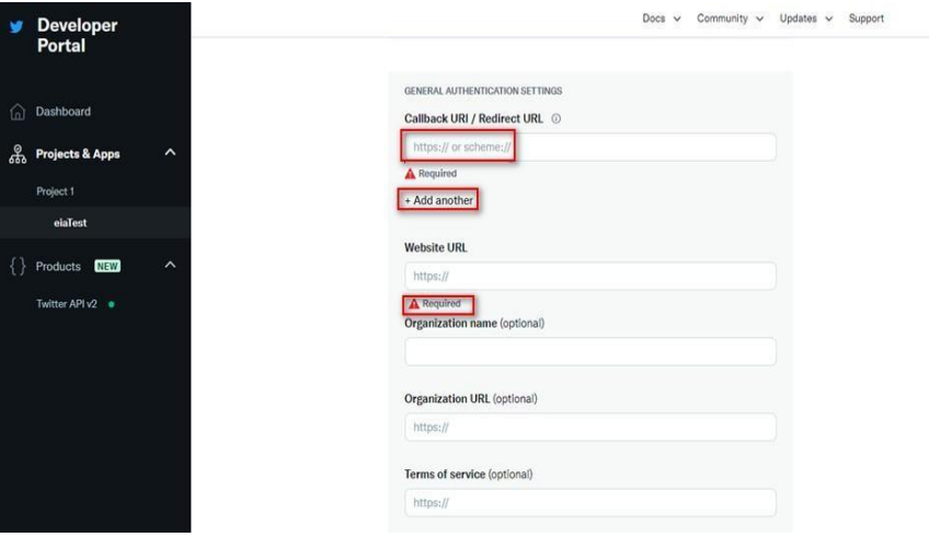
Redirect URL and website URL
Drawing and Parameter Settings
- In the Captive Portal editor, click the Twitter box in the Auth Configuration area and enable Twitter authentication.
- Enter the app ID and app secret of the Twitter app created previously. Configure other options as needed and save the template.
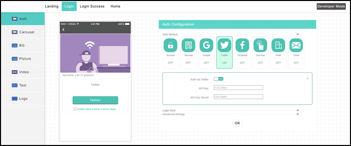
Twitter authentication can be used in combination with:
- Fixed Account authentication.
- Member authentication.
- Facebook authentication.
- Google authentication.
You can use up to three authentication methods simultaneously.
Twitter authentication
After configuring all parameters and completing the portal design for this authentication method, it will not be active on your network yet. For clients to start being directed to your captive portal, it is necessary to complete the final step of linking the generated template to the desired SSID. Please refer to the detailed step-by-step guides in the Direct Creation and Linking on SSID or Linking Template via Service menu sections.
Configure Voucher authentication
Voucher authentication allows users to connect to the Internet using a temporary access code generated by the system. It is ideal for controlling session durations in hotels, cafes, and events.
1. Drawing and Parameter Settings
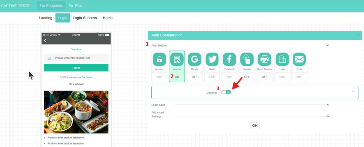
- In the Captive Portal editor, in the Auth Method row, select the Voucher option and enable the configuration.
- In Advanced Settings, configure the time limit options according to your plan:
- Session Timeout: Duration of the session (in minutes). It cannot exceed the daily limit.
- Daily Online Duration: Daily connection limit for a client (maximum of 1440 minutes / 24h).
- Idle Timer: Idle time. The client is disconnected after this period of inactivity (in minutes).
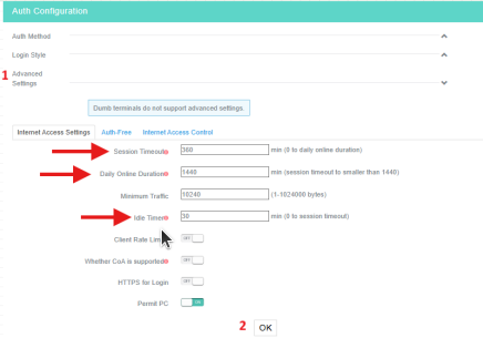
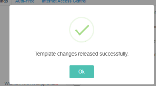
- After configuring these settings, click OK to save the template.
2. Voucher Generation for Authentication
- On the top navigation bar, select Settings > Cloud APs > Users.
- Select a branch and a site at the top of the page.
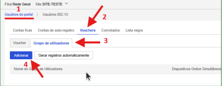
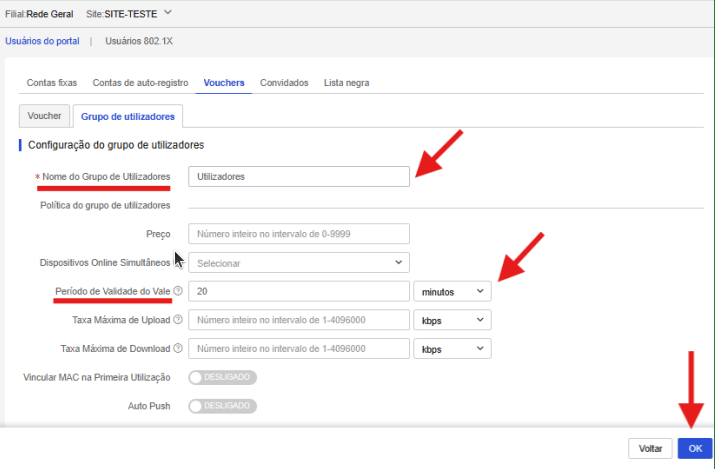
- Access the Voucher tab, click User group, and click Add. Enter the group name and the voucher validity duration. When finished, click OK to save.
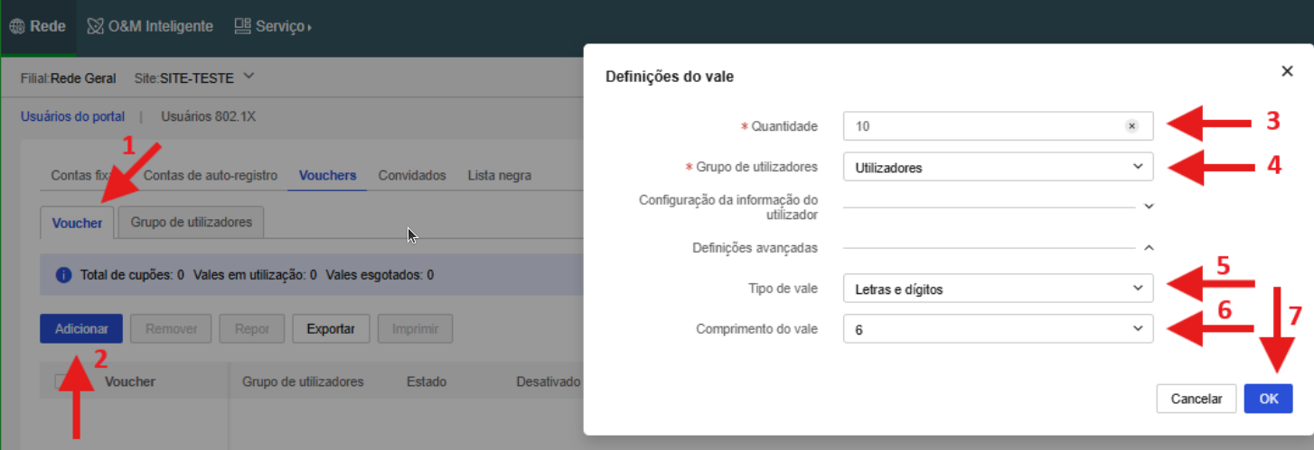
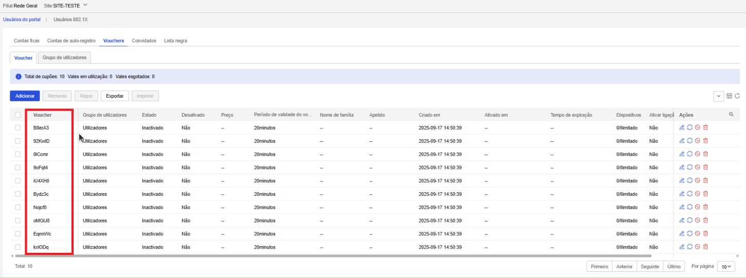
- Access the Voucher tab to generate the codes. Click Add, set the quantity, select the group configured in the previous step, the voucher type, and the character length. Click OK to save. The codes will be visible in the Voucher column.
Next Step: Linking to the SSID
After configuring all parameters and completing the portal design for this authentication method, it will not be active on your network yet. For clients to start being directed to your captive portal, it is necessary to complete the final step of linking the generated template to the desired SSID. Please refer to the detailed step-by-step guides in the Direct Creation and Linking on SSID or Linking Template via Service menu sections.
Configure Hotel authentication
Hotel authentication integrates the login portal with hotel check-in databases, requiring guests to enter details like room number and last name to unlock Internet access.
1. Hotel ID Creation
- On the top navigation bar, click the Service menu.
- Select Authentication > Accounts > Hotel ID to add a hotel.
- To add a hotel, click Add in the Hotel ID tab.
2. Drawing and Parameter Settings
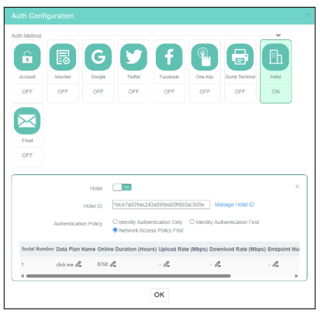
- In the Captive Portal editor, click the Hotel box in the Auth Configuration area and enable Hotel authentication.
- Select the Hotel ID created previously. Configure other control options as needed.
- Click OK and click Release in the upper right corner of the page to save.
After configuring all parameters and completing the portal design for this authentication method, it will not be active on your network yet. For clients to start being directed to your captive portal, it is necessary to complete the final step of linking the generated template to the desired SSID. Please refer to the detailed step-by-step guides in the Direct Creation and Linking on SSID or Linking Template via Service menu sections.
Configure Email authentication
Email authentication requires users to provide a valid email address to receive a one-time access passcode. This method is ideal for validating visitors' contact information.
Drawing and Parameter Settings
- In the Captive Portal editor, click the Email box in the Auth Configuration area and enable Email authentication.
- Confirm the Email authentication, setting the additional session parameters according to your preferences.
- Click OK and click Release in the upper right corner of the page to save.
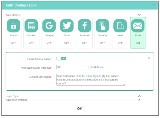
After configuring all parameters and completing the portal design for this authentication method, it will not be active on your network yet. For clients to start being directed to your captive portal, it is necessary to complete the final step of linking the generated template to the desired SSID. Please refer to the detailed step-by-step guides in the Direct Creation and Linking on SSID or Linking Template via Service menu sections.
Configure Facebook authentication
With Facebook authentication enabled, users will be redirected to the Facebook login page for authentication. They will be able to access the network only after granting INC Cloud access to their Facebook information (nickname, profile, and email info).
Creating a Facebook app
- Log in to Meta for Developers at https://developers.facebook.com.
- Click Create app to create a Facebook app.
- Specify the app name.
- Start business verification and finish creation.
- On Meta for Developers, enable Client OAuth Login and Web OAuth Login and enter the login URL as a valid redirect URI.
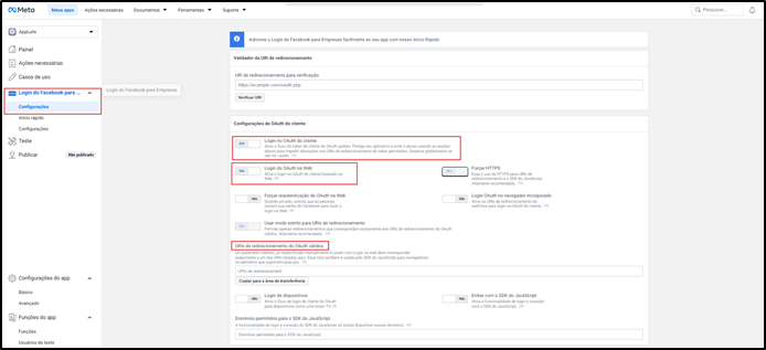
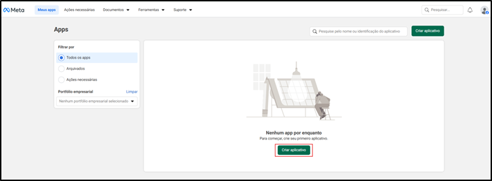
Creating an app
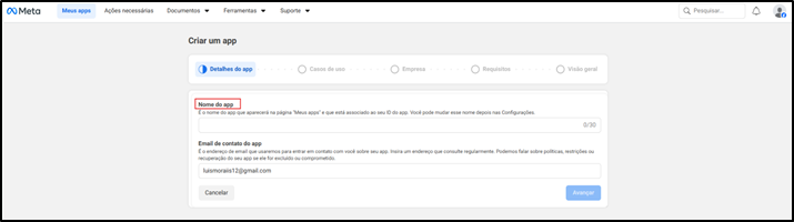
Specifying the app name
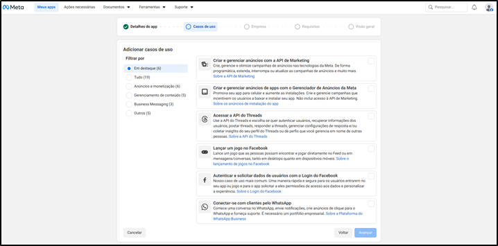
Business verification and finalization
Drawing and Parameter Settings
- In the Captive Portal editor, click the Facebook box in the Auth Configuration area and enable Facebook authentication.
- Enter the app ID and app secret. Configure other options as needed.
- Click OK or Release in the upper right corner of the page to save.
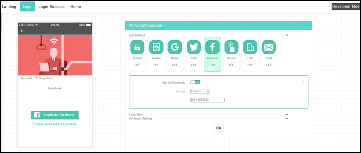
Facebook authentication configuration
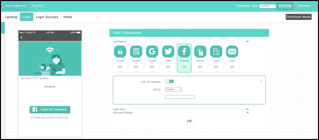
Portal authentication configuration page
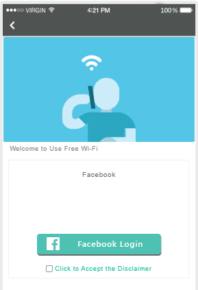
Portal login preview page
Configure Facebook authentication
Important:
» Execute commands in this section after you finish the settings in Configure
general settings or Appendix A Authentication commands for the
device.
» Free-rule 38 might disable the app from displaying pictures. Please configure this rule as
needed or contact technical support.
# Configure destination-based portal-free rules to allow portal users who send an HTTP/HTTPS request that carries Facebook-related host names to access network resources without authentication.
<Sysname> System-View
                        [Sysname] portal free-rule 31 destination facebook.com
                        [Sysname] portal free-rule 32 destination m.facebook.com
                        [Sysname] portal free-rule 33 destination www.facebook.com
                        [Sysname] portal free-rule 34 destination graph.facebook.com
                        [Sysname] portal free-rule 35 destination connect.facebook.net
                        [Sysname] portal free-rule 36 destination static.xx.fbcdn.net
                        [Sysname] portal free-rule 37 destination staticxx.fbcdn.com
                        [Sysname] portal free-rule 38 destination scontent-hkg-3-1.xx.fbcdn.net
Next Step: Linking to the SSID
After configuring all parameters and completing the portal design for this authentication method, it will not be active on your network yet. For clients to start being directed to your captive portal, it is necessary to complete the final step of linking the generated template to the desired SSID. Please refer to the detailed step-by-step guides in the Direct Creation and Linking on SSID or Linking Template via Service menu sections.
Configure combined authentication
Restrictions and guidelines
The following authentication methods can be used together:
- Fixed account authentication.
- Voucher authentication.
- Google authentication.
- Twitter authentication.
- Facebook authentication.
- Email authentication.
A user can access the network as long as they pass one authentication.
Procedure
- Configure settings on the device as described if the software version of the device is lower than 5405.
- Select Service > Authentication > Authentication Templates. Select multiple authentication methods on the design page.
Next Step: Linking to the SSID
After configuring all parameters and completing the portal design for this authentication method, it will not be active on your network yet. For clients to start being directed to your captive portal, it is necessary to complete the final step of linking the generated template to the desired SSID. Please refer to the detailed step-by-step guides in the Direct Creation and Linking on SSID or Linking Template via Service menu sections.
Configure Dumb terminal authentication
Restrictions and guidelines
- If an account group contains accounts that have been authenticated, changing the validity period of the account group changes the validity period of all accounts in the group.
- If you configure the validity period as 0, the account never expires.
- You can enter the first three bytes to add MAC addresses in bulk. The configuration of the validity period of a full MAC address and that of a three-byte MAC address are not mutually exclusive. Suppose you add MAC addresses that start with AA-BB-CC and specify a validity period of 5 days, and then add the MAC address AA-BB-CC-11-22-33 and specify a validity period of 10 days. The validity periods of Dumb terminals with a MAC address of AA-BB-CC-11-22-33 and a MAC address that starts with AA-BB-CC are 10 and 5 days, respectively.
Procedure
- On the top navigation bar, click Service.
- Select Authentication in the navigation panel and click the Accounts tab.
- On the Dumb Terminal Accounts tab, click Edit Account Group.
- Click Add.
- Enter the required info and click OK.
- Select an account group and click Add.
- Enter a MAC address in the required format.
- In the Captive Portal editor, click the Dumb terminal box in the Auth Configuration area and enable Dumb terminal authentication.
- Select the account group created in the previous step.
- Click OK or Release in the upper right corner of the page to save.
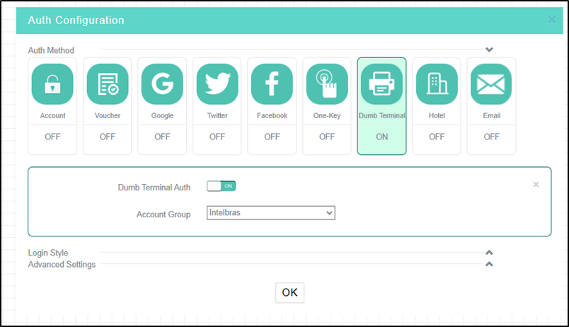
Dumb terminal authentication configuration
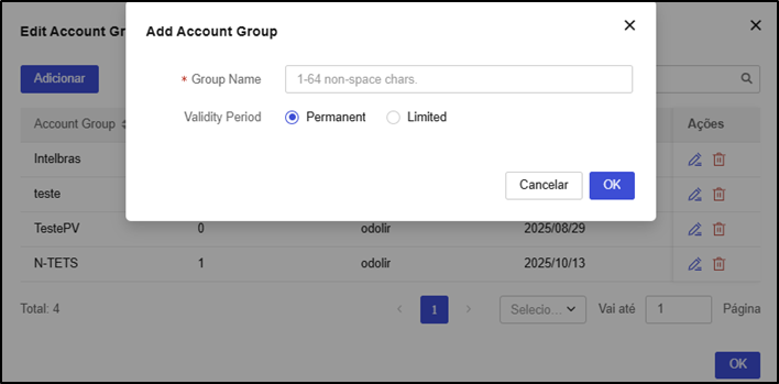
Adding an account group
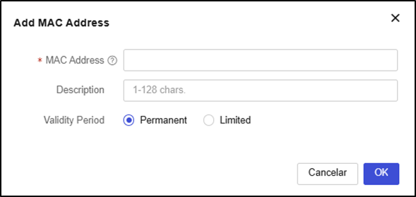
Adding a MAC address
After configuring all parameters and completing the portal design for this authentication method, it will not be active on your network yet. For clients to start being directed to your captive portal, it is necessary to complete the final step of linking the generated template to the desired SSID. Please refer to the detailed step-by-step guides in the Direct Creation and Linking on SSID or Linking Template via Service menu sections.
Configure bulk authentication
Perform this task to implement bulk authentication settings.
Restrictions and guidelines
- The configuration of a bulk authentication template takes precedence over that of a non-bulk authentication template. For the non-bulk authentication template to take effect, click the Edit icon for that template and then click Apply.
- Before implementing the bulk configuration, make sure the following requirements are met:
- The devices on which bulk authentication is deployed are online. If one is offline, the implementation will fail for it.
- The wireless service name is the same as the portal web server name.
Procedure
- After creating and designing the authentication template, on the template list screen (Service > Authentication), click the Deploy Template icon in the Actions column of the corresponding record.
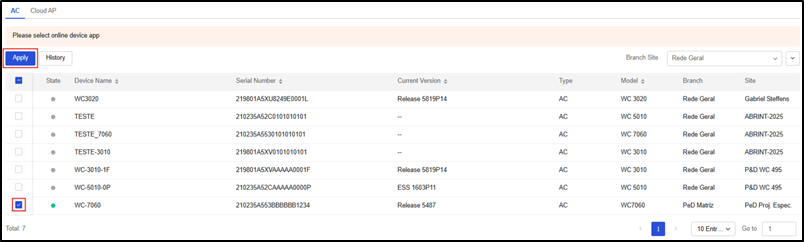
- In the window that opens, click the ACs tab.
- Select the desired branch or location.
- Select the corresponding device or site and click Apply.
After configuring all parameters and completing the portal design for this authentication method, it will not be active on your network yet. For clients to start being directed to your captive portal, it is necessary to complete the final step of linking the generated template to the desired SSID. Please refer to the detailed step-by-step guides in the Direct Creation and Linking on SSID or Linking Template via Service menu sections.
Customize authentication page
You can configure the landing page, login page, login success page, and home page, and you can push or disable the landing page or login success page as needed.
Restrictions and guidelines
- The image size cannot exceed 1 M. As a best practice, set the image size between 100 KB and 200 KB. Only JPG, JPEG, BMP, PNG, GIF, and SVG formats are allowed.
- As a best practice to avoid affecting page loading speed, do not add too many controls.
Procedure
- In the Captive Portal editor (template design screen), configure the settings shown in the Preview of configuration changes:
- Logo: the aspect ratio must be 1:1. The image will be automatically cropped into a circle. You can enter a store name shorter than 12 characters.
- Background: the aspect ratio must be 3:5.
- Carousel: the aspect ratio must be 11:5. Two or three images with the same height are required.
- Image: the aspect ratio must be 11:5. The image description cannot exceed 48 characters.
- Video: the video size cannot exceed 5 M. Only MP4, WEBM, and OGG formats are allowed.
- Text: you can edit the font, font size, bold, and font color.
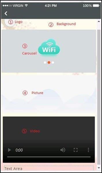
Description of custom template
- To configure the home page, click the Home tab and select Use custom link.
- Enter a custom link and click Upload.
- To preview the link, click Preview in the upper right corner of the page.
Link Captive Portal to SSID (Service menu)
The steps to link the created authentication portal template to multiple SSIDs via the Service menu are described below.
- Return to the Service > Authentication screen.
- On the created template, click the Issue Template button at the end of the registry row.
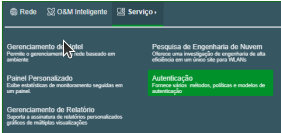
- Select the Cloud AP option, choose the Site, and click Apply.
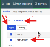
- Select the registered SSID code and confirm the change.
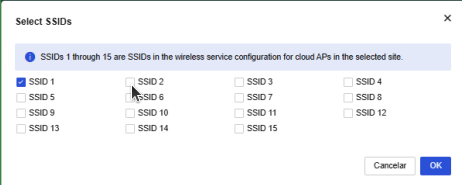
Note: To find out which SSID code to link, go to Network > Settings > Cloud APs > WLAN Settings > Wi-Fi Settings and check the number registered in the Num column.
- Confirm the linking by accessing the SSID settings and checking if the Cloud-integrated authentication option is checked with the name of the created portal.
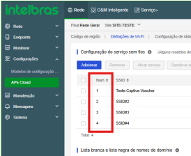
Edit an existing Captive Portal template
If you need to change the design, colors, logo, terms of use, or the authentication method of a Captive Portal that has already been created, the procedure varies depending on the creation route used:
Method 1: Edit template created via the Service menu
- In the top menu, go to Service > Authentication.
- On the Portal Authentication screen (central library), locate the template you want to modify in the table.
- In the Actions column, click the Edit icon
 (pencil) next to it.
 - Make the desired changes in the graphic editor and, in the upper right corner of the screen, click OK or Release to save and release the changes made to the template.
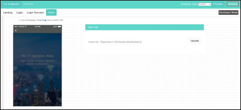
- Go back to the templates library under Service > Authentication.
- Reapply the template to the SSID by executing the issue process again: click Issue Template at the end of the template's registry row, select the Site, and link it back to the target SSIDs.
Synchronization Best Practices: To ensure that INC Cloud has successfully pushed the update to the APs immediately, navigate to Network > Settings > Cloud APs > WLAN Settings > Wi-Fi Settings, locate the linked SSID in the list, click Edit (pencil icon), and without changing any fields, click the OK button directly at the bottom of the modal. This will force the synchronization and correct provisioning of the network.
Method 2: Edit template created directly on the SSID
- On the left sidebar, navigate to Network > Settings > Cloud APs > WLAN Settings and make sure you are on the Wi-Fi Settings tab.
- In the wireless networks table, locate the SSID associated with the Captive Portal you want to modify.
- In the Actions column, click the Draw icon
 (brush/canvas).
 - The graphic editor will open immediately. Make the desired visual changes and click OK or Release in the upper right corner to save (edits take effect immediately for this wireless network).
Important: If the SSID is using a template that was created and linked globally via the Service > Authentication menu, you will not be able to edit it using the draw icon on the SSID screen. In this scenario, you must use Method 1 to make the edits directly in the centralized template library.
Configure advanced settings
INC Cloud provides advanced authentication settings to simplify authentication management, reduce costs, and optimize market promotion. The INC Cloud Advanced Authentication Features table describes the advanced features available for each authentication method. You can configure these settings as needed.
INC Cloud advanced authentication features:
| Authentication method | Advanced features |
|---|---|
| One-key authentication | Captive bypass Hide and customize the One-key authentication button Internet access settings Free authentication Cross-site and cross-SSID re-authentication Developer mode Internet access control Domain name blacklist View and export authentication configuration deployment history |
| Fixed account authentication | Captive bypass Bulk account management Self-service password change Collaboration with LDAP server Change visual effects of the login page Internet access settings Free authentication Cross-site and cross-SSID re-authentication Developer mode Internet access control Domain name blacklist View and export authentication configuration deployment history |
| Dumb terminal authentication | Captive bypass Dumb terminal account group management Developer mode Domain name blacklist View and export authentication configuration deployment history |
Activate the captive-bypass feature
Normally, the device automatically sends the authentication page to a client when the client attempts to access the portal of an authentication network. The captive-bypass feature allows the device to send the portal authentication page to the client only when the user launches a browser.
To activate the captive-bypass feature, you must perform the following steps on the device:
- Enter system view.
system-view - Enter the portal web-server view.
portal web-server Cloud - Enable the captive-bypass feature.
captive-bypass enable
Hide or customize the One-key authentication button
Perform this task to hide the One-key authentication button or change the button style. If the button is hidden, users pass through authentication automatically after the countdown timer on the login page expires.
Restrictions and guidelines
You can change the button style only when the button is not hidden.
Procedure
- On the top navigation bar, click Service.
- Select Authentication > Authentication Templates.
- If you do not have a template or need a new one, click Add.
- To edit an authentication template, click the Edit icon for that authentication template.
- Click the Draw icon for the target authentication template.
- Click the One-Key tile in the Auth Configuration area, and then hide or customize the button as needed.
Manage fixed Accounts
Perform this task to delete, import, or export accounts in bulk. To manage accounts:
- On the top navigation bar, click Network.
- Select Settings > Cloud APs > Users from the navigation pane.
- Click the Portal Users tab and then click the Fixed Accounts tab.
- To delete accounts, select the target accounts and click Delete.
- To import accounts, click Import, download the template file, fill in the file as needed, and then upload the template file.
- To export accounts, click Export.
Enable self-service password change
This feature allows users to change passwords during login.
To enable self-service password change:
- On the top navigation bar, click Service.
- Select Authentication > Authentication Templates.
- If you do not have a template or need a new one, click Add.
- To edit an authentication template, click the Edit icon for that authentication template.
- Click the Draw icon for the target authentication template.
- Click the Account tile in the Auth Configuration area.
- Enable change password.
Allow collaboration with an LDAP server for account verification
Perform this task to allow INC Cloud to report usernames and passwords to the LDAP server for verification when users attempt to access the WLAN using accounts. This frees network administrators from importing account information from the LDAP server to INC Cloud.
Restrictions and guidelines
To use this feature, ensure that the LDAP server has been configured.
Procedure
- On the top navigation bar, click Service.
- Select Authentication > Authentication Templates.
- If you do not have a template or need a new one, click Add.
- To edit an authentication template, click the Edit icon for that authentication template.
- Click the Draw icon for the target authentication template.
- Click the Account tile in the Auth Configuration area.
- Enable LDAP and define the LDAP settings as needed.
- Click LDAP Configuration Verification to verify the LDAP settings.
Change login page visual effect settings
Perform this task to change the background color, background opacity, and text color on the login page.
Restrictions and guidelines
Caution: Restoring default settings will remove all user-defined visual effect settings, and the restoration operation is irreversible. Use this feature with caution.
The visual effect settings of authentication methods take effect only when multiple authentication methods are enabled.
Procedure
- On the top navigation bar, click Service.
- Select Authentication > Authentication Templates.
- If you don't have a template or need a new one, click Add.
- To edit an authentication template, click the Edit icon for that authentication template.
- Click the Draw icon for the target authentication template.
- Click to expand the Login style menu in the Auth Configuration area.
- Configure the background color, background opacity, and text color as required. The adjustment will be displayed in the real-time preview area. To restore the default visual effect settings, click Restore default.
Configure Internet access settings
Procedure
- On the top navigation bar, click Service.
- Select Authentication > Authentication Templates.
- If you don't have a template or need a new one, click Add.
- To edit an authentication template, click the Edit icon for that authentication template.
- Click the Draw icon for the target authentication template.
- Click to expand the Advanced settings menu in the Auth Configuration area.
- Configure Internet access settings as needed.
Parameters
- Session timeout: Maximum continuous online duration of a client after one authentication. A client will be disconnected when its continuous online duration exceeds the timeout. The session timeout cannot be greater than the daily online duration.
- Daily online duration: Maximum online duration of a client in one day. A client will be disconnected when its online duration for a day exceeds the limit. The daily online duration cannot be less than the session timeout.
- Minimum traffic and idle timer: Logs off a client if the traffic within an idle timer does not reach the minimum traffic threshold. Configuring the idle timer as 0 disables the idle timer feature.
Caution: As a best practice, set the idle time to a value no greater than half of the clients' IP address lease, allowing offline client entries to be deleted in time.
- Client Rate Limit: Traffic rate limit for uplink and downlink clients. This feature is supported by versions higher than 5417P01.
- HTTPS for landing and login: Use HTTPS sessions for the landing and login page.
- Allow PC: Allow PCs to access the WLAN. Facebook authentication does not support this feature.
Manage dumb terminal account groups
Perform this task to create, delete, or edit dumb terminal account groups and import or export dumb terminal account groups.
If you enable dumb terminal authentication and specify an account group, only dumb terminals in the group can access the WLAN.
To manage dumb terminal account groups:
- On the top navigation bar, click Service.
- Select Authentication from the navigation pane.
- Click the Accounts tab.
- On the Dumb Terminal Accounts tab, configure dumb terminal account groups.
Configure automated portal authentication
This feature allows users who have been authenticated to access the network without re-authentication within the authentication-free period. The following modes are available:
- Portal redirection: In this mode, users must launch a browser to trigger automated portal authentication. This mode supports pushing advertisements to clients.
- MAC trigger: In this mode, users can access the WLAN without launching a browser. This mode does not support pushing advertisements to clients.
Configure portal redirection authentication
- On the top navigation bar, click Service.
- Select Authentication > Authentication Templates.
- If you do not have a template or need a new one, click Add.
- To edit an authentication template, click the Edit icon for that authentication template.
- Click the Draw icon for the target authentication template.
- Click to expand the Advanced settings menu in the Auth Configuration area.
- Click the Free Authentication tab and configure the free authentication feature.
Configure MAC-triggered authentication
Configure portal redirection authentication. For more information, see Configure portal redirection authentication.
Configure MAC-triggered authentication on the device:
- Configure the MAC binding server.
# Create a MAC binding server and enter its view.
<Sysname> System-View
[Sysname] portal mac-trigger-server cloud
# Enable cloud MAC binding authentication. Set the maximum number of MAC binding query attempts to 2 and the query interval to 3 seconds.
[Sysname-portal-mac-trigger-server-cloud] cloud-binding enable
[Sysname-portal-mac-trigger-server-cloud] binding-retry 2 interval 3
[Sysname-portal-mac-trigger-server-cloud] quit
- Apply the MAC binding server Cloud to the service template Cloud.
[Sysname] wlan service-template Cloud
[Sysname-wlan-st-cloud] portal apply mac-trigger-server cloud
Configure cross-site and cross-SSID re-authentication
This feature allows clients that have been authenticated to roam between wireless services without re-authentication. The roaming clients can access the wireless services as long as the re-authentication period does not expire.
These wireless services must use the same authentication template or have the same SSID.
Restrictions and guidelines
This feature is available only for authentication templates configured in the App Center.
Procedure
- On the top navigation bar, click Service.
- Select Authentication from the navigation pane.
- Click the Draw icon for the target authentication template.
- Click to expand the Advanced settings menu in the Auth Configuration area.
- Click the Free Authentication tab and activate free authentication.
- Configure re-authentication between sites and between SSIDs.
Configure Internet access control
Perform this task to specify the time intervals during which users are allowed to access the WLAN.
Restrictions and guidelines
Internet access control is based on hours. It is possible to specify a maximum of five time intervals for one day. To specify a time interval that ends at 24:00, set the end time to 00:00. If you set a time interval from 00:00 to 00:00 for a day, users can access the Internet at any time on that day.
Procedure
- On the top navigation bar, click Service.
- Select Authentication > Authentication Templates.
- If you don't have a template or need a new one, click Add.
- To edit an authentication template, click the Edit icon for that authentication template.
- Click the Draw icon for the target authentication template.
- Click to expand the Advanced settings menu in the Auth Configuration area.
- Click the Internet Access Control tab and specify the time intervals.
Configure developer mode
Caution: Editing existing function codes may disable INC Cloud authentication. Use this feature with caution.
Enable authentication for customization purposes.
Procedure
- On the top navigation bar, click Service.
- Select Authentication > Authentication Templates.
- If you don't have a template or need a new one, click Add.
- To edit an authentication template, click the Edit icon for that authentication template.
- Click the Draw icon for the target authentication template.
- Click Developer mode in the upper right corner.
Configure domain name blacklist
Restrictions and guidelines
This feature takes effect only when wireless authentication is configured.
Procedure
- On the top navigation bar, click Network.
- Select Settings > Routers > Authentication in the navigation pane.
- Select a branch, a site, and a device from the top of the page.
- Click the Domain name blacklist tab to configure the blacklist.
View or export authentication template deployment history
Perform this task to view the history of all authentication template deployments or deployments for the current day, last 7 days, or last 30 days.
To view or export the authentication template deployment history:
- On the top navigation bar, click Service.
- Select Authentication from the navigation pane.
- On the Authentication Templates tab, click the Issue Template icon for the target authentication template.
- Click the Cloud AP tab to view the deployment history of a Cloud AP.
Special scenarios
This section describes configurations applicable to specific network scenarios, such as portal behavior in case of authentication failure and deployments where APs or ACs operate on a public network.
Portal fail-permit
This feature is available only in scenarios with an AC or wireless router as the authenticator.
Portal fail-permit allows users to access the network without portal authentication when the access device detects that the portal authentication server or the portal Web server is unreachable.
After portal authentication resumes, unauthenticated users must pass portal authentication to access the network. Users who passed portal authentication before the fail-permit event can continue accessing the network.
Restrictions and guidelines
To use this feature, ensure you have configured basic settings on the device.
For more information, see Configure settings on the device.
Procedure
Enable portal fail-permit.
                        <Sysname> System-View
                        [Sysname] wlan service-template Cloud
                        [Sysname-wlan-st-cloud] portal fail-permit web-server
                        [Sysname-wlan-st-cloud] quit
Configure portal Web server detection.
Caution: To avoid portal server flapping, follow the provided order to configure portal Web server detection.
Specify the URL and detection type for the portal Web server.
                        [Sysname] portal web-server cloud
                        [Sysname-portal-websvr-cloud] server-detect url  http://inccloud-captive.intelbras.com.br/portal/ping detect-type http
Configure server detection:
- Set the detection interval to 600 seconds.
- Set the maximum number of consecutive detection failures to 2.
- Configure the device to send a log message and a trap message after the reachability status of the server changes.
                        [Sysname-portal-websvr-cloud] server-detect interval 10 retry 2 log trap
                        [Sysname-portal-websvr-cloud] quit
AP/AC on public network
This feature is available only in scenarios with an AC or wireless router as the authenticator.
By default, the device provides HTTP port 80 for clients to exchange authentication packets. With local forwarding enabled, if APs register with the AC through the public network and port 80 is unavailable, perform this task to configure CMCC or change the HTTP service port for clients to perform INC Cloud authentication.
Configure CMCC
You must configure CMCC on the AC and on INC Cloud. To configure CMCC:
- Configure the CMCC protocol
- Configure INC Cloud:
- Configure INC Cloud in an AC+fit AP network
- Configure INC Cloud in a wireless router network
- Configure the device
- Configure INC Cloud:
- (Optional) Configure CMCC portal redirection authentication
- Configure INC Cloud
- Configure the device
Configure the CMCC protocol
Restrictions and guidelines
With CMCC configured, session timeout, daily online duration, and minimum traffic and idle timer settings are unavailable.
Configure INC Cloud in an AC+fit AP network
- On the top navigation bar, click Network.
- Select Settings > ACs > Authentication from the navigation pane.
- Select a branch, a site, and a device from the top of the page.
- Click the Draw icon for the target authentication template.
- Click to expand the Advanced Settings menu in the Auth Configuration area.
- Click the Internet Access Settings tab.
- Configure the CMCC protocols.
Configure INC Cloud in a wireless router network
- On the top navigation bar, click Service.
- Select Authentication > Authentication Templates.
- If you do not have a template or need a new one, click Add.
- To edit an authentication template, click the Edit icon for that authentication template.
- Click the Draw icon for the target authentication template.
- Click to expand the Advanced Settings menu in the Auth Configuration area.
- Click the Internet Access Settings tab.
- Configure the CMCC protocols.
Configure the device
Create a portal authentication server Cloud and enter its view.
                        <Sysname> System-View
                        [Sysname] portal server cloud
Specify 139.217.11.74 as the IPv4 address of the portal authentication server.
[Sysname-portal-server-cloud] ip 139.217.11.74
Specify the portal authentication server type as CMCC.
[Sysname-portal-server-cloud] server-type cmcc
Configure the device to send registration packets to the portal authentication server at 60-second intervals.
                        [Sysname-portal-server-cloud] server-register interval 60
                        [Sysname-portal-server-cloud] quit
Configure CMCC portal redirection authentication
Configure INC Cloud
Enable portal redirection authentication. For more information, see Configure portal redirection authentication for AC+fit AP networks and Configure portal redirection authentication for wireless networks with a wireless router as the authenticator.
Configure the device
Ensure you have configured basic settings on the device. For more information, see Configure settings on the device.
To configure the device:
Configure the MAC binding server.
Caution: To avoid affecting wireless services, you must specify a dedicated MAC binding server for CMCC, even if a MAC binding server has already been created.
Create the MAC binding server mts and enter its view.
                        <Sysname> System-View
                        [Sysname] portal mac-trigger-server mts
Specify the IP address of the MAC binding server as 139.217.11.74.
[Sysname-portal-mac-trigger-server-mts] ip 139.217.11.74
Specify the MAC binding server type as CMCC.
[Sysname-portal-mac-trigger-server-mts] server-type cmcc
(Optional) Set the free traffic threshold for portal users, in bytes.
                        [Sysname-portal-mac-trigger-server-mts] free-traffic threshold 1
                        [Sysname-portal-mac-trigger-server-mts] quit
Bind the MAC binding server mts to the service template Cloud.
                        [Sysname] wlan service-template Cloud
                        [Sysname-wlan-st-cloud] portal apply mac-trigger-server mts
Configure authorization attributes for users in the ISP domain.
Create an ISP domain cloud.
[Sysname] domain cloud
Set the idle timer, in minutes.
[Sysname-isp-cloud] authorization-attribute idle-cut 30
Set the session timeout, in minutes.
                        [Sysname-isp-cloud] authorization-attribute session-timeout 360
                        [Sysname-isp-cloud] quit
Change the HTTP service port
Before performing this task, ensure you have configured basic settings on the device. For more information, see Configure settings on the device.
To change the HTTP service port:
Set the HTTP service port number. In this example, the port number is 8088.
                        <Sysname> System-View
                        [Sysname] ip http port 8088
Create an HTTP-based local portal Web service and set the listening port number to 8088.
                        [Sysname] portal local-web-server http
                        [Sysname-portal-local-websvr-http] tcp-port 8088
                        [Sysname-portal-local-websvr-http] quit
Configure the portal server.
Configure the portal Web server URL. x.x.x.x represents the network egress IP where the AC resides.
                        [Sysname] portal web-server cloud
                        [Sysname-portal-websvr-cloud] url  http://inccloud-captive.intelbras.com.br/portal/protocol?redirect_uri=http://x.x.x.x:8088/portal/cloudlogin.html
Configure the INC Cloud server to redirect users to x.x.x.x:8088.
                        [Sysname-portal-websvr-cloud] if-match original-url http://captive.apple.com user-agent Mozilla temp-pass redirect-url  http://inccloud-captive.intelbras.com.br/portal/protocol?redirect_uri=http://x.x.x.x:8088/portal/cloudlogin.html
                        [Sysname-portal-websvr-cloud] if-match original-url http://www.apple.com user-agent Mozilla temp-pass redirect-url  http://inccloud-captive.intelbras.com.br/portal/protocol?redirect_uri=http://x.x.x.x:8088/portal/cloudlogin.html
[Sysname-portal-websvr-cloud] quit
APPENDIX A - AUTHENTICATION COMMANDS FOR THE DEVICE
This section describes the commands that need to be executed on the device for one-key, account, Facebook, dumb terminal, and guest authentication.
For application and Facebook authentication, you must configure settings in Configure Facebook authentication and Configure Facebook authentication, respectively, after completing the settings in this section.
To quickly execute these commands on the device, edit the highlighted sections as needed and paste all commands in the device's user view.
Note:
» Execute these commands only on versions earlier than 5405. Version 5405 and later support
automatic deployment of authentication configuration to devices and do not require manual
configuration of these commands.
» Ensure that the commands do not conflict with the existing configuration on the device.
» Ensure you have completed the configuration prerequisite tasks. For more information, see
Prerequisites.
                        system-view
                        domain cloud
                        authentication portal none
                        authorization portal none
                        accounting portal none
                        quit

                        portal web-server cloud
                        url  http://inccloud-captive.intelbras.com.br/portal/protocol
                        server-type oauth

                        if-match user-agent CaptiveNetworkSupport redirect-url  http://inccloud-captive.intelbras.com.br/generate_404
                        if-match user-agent Dalvik/2.1.0(Linux;U;Android7.0;HUAWEI redirect-url  http://inccloud-captive.intelbras.com.br/generate_404
                        if-match original-url http://captive.apple.com user-agent Mozilla temp-pass redirect-url  http://inccloud-captive.intelbras.com.br/portal/protocol
                        if-match original-url http://www.apple.com user-agent Mozilla temp-pass redirect-url  http://inccloud-captive.intelbras.com.br/portal/protocol
                        if-match original-url http://10.168.168.168 temp-pass
                        captive-bypass ios optimize enable
                        quit

                        wlan service-template cloud
                        portal enable method direct
                        portal domain cloud portal
                        apply web-server cloud
                        portal temp-pass period 20 enable
                        quit

                        portal local-web-server http quit
                        portal local-web-server https quit

                        ip http enable
                        ip https enable
                        portal host-check enable
                        portal user log enable
                        portal free-rule 1 destination ip 114.114.114.114 255.255.255.255
                        portal free-rule 2 destination ip any udp 53
                        portal free-rule 3 destination ip any tcp 53
                        portal free-rule 4 destination ip any tcp 5223
                        portal free-rule 5 destination oasisauth.intelbras.com
                        portal free-rule 10 destination short.weixin.qq.com
                        portal free-rule 11 destination mp.weixin.qq.com
                        portal free-rule 12 destination long.weixin.qq.com
                        portal free-rule 13 destination dns.weixin.qq.com
                        portal free-rule 14 destination minorshort.weixin.qq.com
                        portal free-rule 15 destination extshort.weixin.qq.com
                        portal free-rule 16 destination szshort.weixin.qq.com
                        portal free-rule 17 destination szlong.weixin.qq.com
                        portal free-rule 18 destination szextshort.weixin.qq.com
                        portal free-rule 19 destination isdspeed.qq.com
                        portal free-rule 20 destination wx.qlogo.cn
                        portal free-rule 21 destination wifi.weixin.qq.com
                        portal free-rule 22 destination open.weixin.qq.com

                        portal safe-redirect enable
                        portal safe-redirect method get post
                        portal safe-redirect user-agent Android
                        portal safe-redirect user-agent CFNetwork
                        portal safe-redirect user-agent CaptiveNetworkSupport
                        portal safe-redirect user-agent MicroMessenger
                        portal safe-redirect user-agent Mozilla
                        portal safe-redirect user-agent iPhone
                        portal safe-redirect user-agent micromessenger
Remote Access
The Remote Access feature of Intelbras INC Cloud allows network administrators to access the web management interface of local devices (such as cameras, DVRs, switches, or other network equipment) remotely and securely over the Internet, without needing to be on the same local network as the equipment or configure complex port forwarding rules on the edge router.
Through an intermediate device already registered on the platform (such as a Cloud Access Point), INC Cloud establishes a secure encrypted tunnel that redirects HTTP, HTTPS, or TCP requests from the administrator's browser directly to the local target device.
Environment Setup (Prerequisites)
- An intermediate device (e.g., Cloud AP) with a firmware version that contains the Remote Access feature.
- The intermediate device must be online and correctly registered and active on the INC Cloud platform.
- Active and functional local network connectivity between the intermediate device and the target device.
Remote Access Configuration
This section describes how to add, edit, access, and remove devices from the INC Cloud remote access list.
Adding a device
To add a new device to be accessed remotely, follow the steps below:
- Go to Maintenance > Remote Access in the INC Cloud side menu.
- Select the site and click the Add button.
- Fill in the form fields:
- Access Name: define an identification name for this remote access.
- Description: add a complementary description to facilitate equipment identification (optional, up to 200 characters).
- Intermediate Device: select the device registered on the platform that will serve as the intermediate point for the access tunnel.
- Dest Device: enter the IP address of the target device. There are two options:
- Automatic Scan (Auto Scanning): the system queries the local DHCP server client table of the intermediate Access Point. It will only detect devices that obtained a dynamic IP address directly from the AP. Devices with a static IP or configured on another local DHCP server will not be listed automatically and must be entered manually.
- Manual Entry (Manual Input): manually enter the IP address of the target device. After entering the IP, click the Ping button to test network connectivity between the intermediate device and the target device before saving.
- Access Type: select the access protocol for the target device's web interface or service (HTTP, HTTPS, or TCP).
- Dest Port: enter the port of the target device. The port is filled automatically based on the selected protocol but can be adjusted manually.
- Sub-Domain Name: define the subdomain address for the access tunnel:
- Random: the platform automatically generates a unique, random subdomain.
- Custom: define your own custom subdomain. It must be between 2 and 30 characters, containing only letters, numbers, and hyphens (-), and cannot start or end with a hyphen.
Note: the intermediate device must have a firmware version that contains the Remote Access feature to work.
- Click OK to save the configuration and enable remote access for the device.
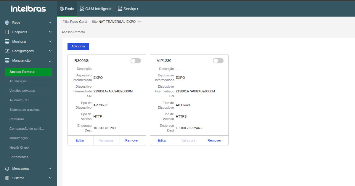
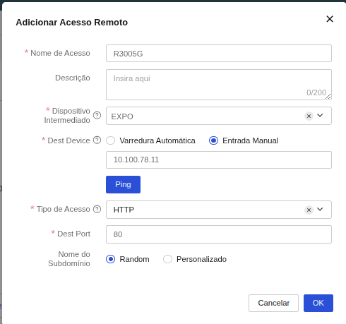
Editing a device
If you need to change the settings of a device already registered in the remote access list:
- Locate the registered device card on the Remote Access page.
- Click the Edit button located in the bottom-left corner of the card's footer.
- Modify the desired fields in the form (such as Access Name, Description, Intermediate Device, Dest Device IP, Access Type/Protocol, Dest Port, or the Sub-Domain Name format).
- Click OK to save the changes. The active tunnel will reboot automatically if active to apply settings.
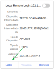
Accessing a device
To establish the connection and remotely access the web interface of the configured equipment:
- Locate the device card on the Remote Access page.
- Enable the toggle switch at the top-right of the device card to establish the connection and activate the tunnel. Remote access will be initially active for 3 hours, turning off automatically after this period.
- Click the Go Now button at the bottom of the card to open remote access.
- Valid To: displays the expiration date and time of the current remote access session. Click the Extend button to extend the validity of the active connection (the maximum continuous time the session can stay active is 24 hours).
- External Network Address: displays the public URL generated for the tunnel. Click Copy to copy the external connection link to your clipboard. You can access the device remotely from anywhere just by having this link.
- A new tab will open in your web browser directing to the external address generated by the tunnel (e.g., `http://example.nat.inccloud.intelbras.com.br`).
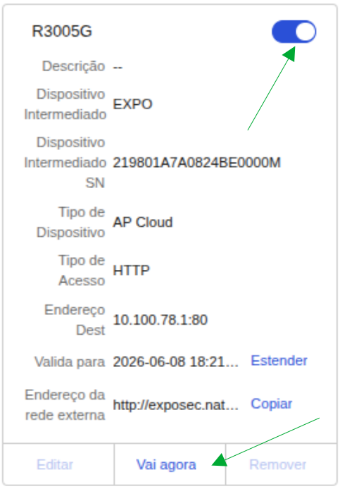
Security Note (Certificate Warning): When accessing a device remotely (especially via HTTPS), your browser may display a "Connection not secure" or "Invalid certificate" warning.
Why does this happen?
This happens because local network devices (such as switches, routers, and cameras) use self-signed SSL certificates generated by their own firmware (or do not have a certificate associated with the tunnel's external domain). Because the browser cannot validate this certificate's identity through a publicly trusted Certificate Authority for the dynamic tunnel address (e.g., `*.nat.inccloud.intelbras.com.br`), it displays the security alert.
This is exactly the same behavior and warning you would get if you were physically accessing the equipment on your private network via its local IP address (e.g., `https://192.168.1.1`). The data transmission through the INC Cloud tunnel remains encrypted and secure. Therefore, you can safely bypass the browser warning (usually by clicking "Advanced" and then "Proceed to..." or "Accept the risk and continue") without any risk.
Removing a device
To delete a device from the site's remote access list:
- Locate the device card on the Remote Access page.
- Click the Remove button located in the bottom-right corner of the card's footer.
- Confirm the removal in the security dialog box to complete the process.
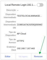
Notice: Removing the device from the remote access list does not affect the device's operation on the local network. Only the remote access link and its subdomain will be deleted from the platform.
FAQ
I have successfully modified and deployed the authentication template settings. Why do the previous settings still take effect for clients that go online after deployment?
Verify that the settings were modified and deployed successfully. If the problem persists, clear the browser's access records and cache on the client.
The Authentication Templates page in the App Center does not display the devices available for template deployment. What should I do?
Verify that the device version meets the requirements. If not, upgrade the device to the latest version.
How can I change the SSID of a wireless service?
Change the Wi-Fi name in INC Cloud. For AC+fit AP networks, you can also change the Wi-Fi name in the AC. Unbind and then re-bind the service template from the authentication service.
How can I update my INC Cloud to use newly released features?
Features in INC Cloud are updated automatically and do not require manual operations. For new features in the authentication template, you might need to reconfigure and then release the template for the new features to take effect.
Why can a client go offline and then go online without being authenticated, even if free authentication is not configured?
The system does not remove the client entry from the authenticated client list immediately after a client disassociation event. The entry will not be removed until the idle timer expires or the administrator logs off the client. An offline client can go online without being authenticated if its entry still exists.
You can view client entries in INC Cloud or by executing the display portal user all
command.
Why does the number of authenticated clients exceed the total number of online clients?
This symptom occurs when a client has just gone offline. The system does not remove the client entry from the authenticated client list immediately after a client disassociation event. The entry will not be removed until the idle timer expires or the administrator manually logs off the client.
I configured the authentication settings on the device and in INC Cloud as required. The client access attempt can trigger portal authentication but fails to open the redirection page. What should I do?
This problem can occur if the network segment of the client's IP address is unknown to uplink
devices and packets cannot be transmitted back. To resolve this problem, configure the
nat outbound command on the device interface that connects the device to the
external network or use IGP to advertise the network segment in the network.
iOS clients cannot trigger authentication even if optimized captive-bypass is enabled. What should I do?
Execute the portal captive-bypass optimize delay seconds command to set the
captive-bypass protection timeout. The value range is 6 to 60 seconds and the default value is 6
seconds.
To avoid affecting device performance, do not set the timeout to a very high value.

Customer support: (48) 2106 0006
Forum: forum.intelbras.com.br
Chat support: intelbras.com.br/suporte-tecnico
Email support: suporte@intelbras.com.br
SAC: 0800 7042767
Intelbras S/A – Indústria de Telecomunicação Eletrônica Brasileira
Rodovia SC 281, km 4,5 – Sertão do Maruim – São José/SC - 88122-001
CNPJ 82.901.000/0014-41 - www.intelbras.com.br
Brazilian Industry